| Tweet |

Custom Search
|
|
 
|
||
|
ENGINE LATHE TOOLS.Figure 9-7 shows the most popular shapes of ground lathe cutter bits
and their applications. In the following paragraphs we will discuss each of the
types shown.
Left-Hand Turning Tool.This tool is ground for machining work when it is fed from left to right, as indicated in figure 9-7, view A. The cutting edge is on the right side of the tool, and the top of the tool slopes down away from the cutting edge.
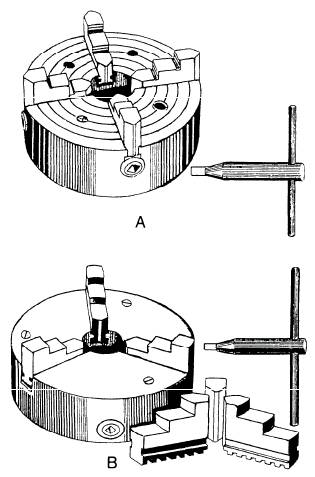
Figure 9-8.A. Four-Jaw chuck. B. Three-Jaw chuck. Round-Nosed Turning Tool.This tool is for general-purpose machine work and is used for taking light roughing cuts and finishing cuts. Usually, the top of the cutter bit is ground with side rake so the tool may be fed from right to left. Sometimes this cutter bit is ground flat on top so the tool may be fed in either direction (fig. 9-7, view B). Right-Hand Turning Tool.This is just the opposite of the left-hand turning tool and is designed to cut when it is fed from right to left (fig. 9-7, view C). The cutting edge is on the left side. This is an ideal tool for taking roughing cuts and for all-around machine work. Left-Hand Facing Tool.This tool is intended for facing on the left-hand side of the work (fig. 9-7, view D). The direction of feed is away from the lathe center. The cutting edge is on the right-hand side of the tool, and the point of the tool is sharp to permit machining a square corner. Threading Tool.The point of the threading tool is ground to a 60-degree included angle for machining V-form screw threads (fig. 9-7, view E). Usually, the top of the tool is ground flat, and there is clearance on both sides of the tool so it will cut on both sides. Right-Hand Facing Tool.This tool is just the opposite of the left-hand facing tool and is intended for facing the right end of the work and for machining the right side of a shoulder (fig. 9-7, view F). Square-Nosed Parting (Cutoff) Tool.The principal cutting edge of this tool is on the front (fig. 9-7, view G). Both sides of the tool must have sufficient clearance to prevent binding and should be ground slightly narrower at the back than at the cutting edge. This tool is convenient for machining necks and grooves and for squaring comers and cutting off. Boring Tool.The boring tool (fig. 9-7, view H) is usually ground the same shape as the left-hand turning
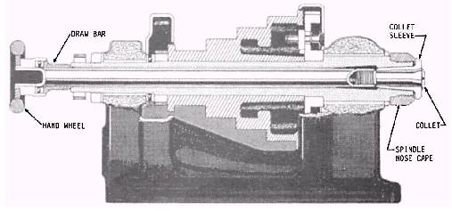
Figure 9-9.Draw-in collet chuck.
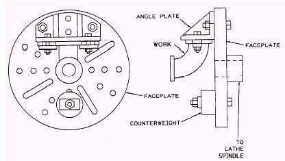
Figure 9-10.Faceplate. tool so that the cutting edge is on the right side of the cutter bit and may be fed in toward the headstock. Inside-Threading Tool.The inside-threading tool (fig. 9-7, view J) has the same shape as the threading tool in figure 9-7, view E, but it is usually much smaller. Boring and inside-threading tools may require larger relief angles when used in small diameter holes. LATHE CHUCKS.The lathe chuck is a device for holding lathe work. It is mounted on the nose of the spindle. The work is held by jaws which can be moved in radial slots toward the center of the chuck to clamp down on the sides of the work. These jaws are moved in and out by screws turned by a special chuck wrench. The four-jaw independent lathe chuck, view A in figure 9-8, is the most practical chuck for general work The four jaws are adjusted one at a time, making it possible to hold work of various shapes and to adjust the center of the work to coincide with the axis of the spindle. The jaws are reversible. The three-jaw universal or scroll chuck, view B in figure 9-8, can be used only for holding round or hexagonal work All three jaws move in and out together in one operation and bring the work on center automatically. This chuck is easier to operate than the four-jaw type, but, when its parts become worn, its accuracy in centering cannot be relied upon. Proper lubrication and constant care are necessary to ensure reliability. The draw-in collet chuck is used to hold small work for machining in the lathe. It is the most accurate type of chuck made and is intended for precision work. Figure 9-9 shows the parts assembled in place in the lathe spindle. The collet, which holds the work, is a split-cylinder with an outside taper that fits into the tapered closing sleeve and screws into the threaded end of the hollow drawbar. As the handwheel is turned clockwise, the drawbar is moved toward the handwheel. This tightening up on the drawbar pulls the collet back into the tapered sleeve, thereby closing it firmly over the work and centering the work accurately and quickly. The size of the hole in the collet determines the diameter of the work the chuck can handle. The faceplate is used for holding work that, because of its shape and dimensions, cannot be swung between centers or in a chuck. The T-slots and other openings on its surface provide convenient anchors for bolts and clamps used in securing the work to it. The faceplate is mounted on the nose of the spindle. (See fig. 9-10.) The driving plate is similar to a small faceplate and is used mainly for driving work that is held between centers. The primary difference between a faceplate and a driving plate is that a faceplate has a machined face for precision mounting, while the face of a driving plate is left rough. When a driving plate is used, the bent tail of a dog clamped to the work is inserted into a slot in the faceplate. This transmits rotary motion to the work.
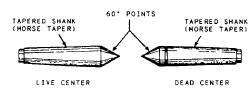
Figure 9-11.60-degree lathe centers.
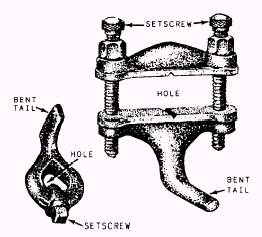
Figure 9-12.Lathe dogs. |
 
|
|
|
||