| Tweet |

Custom Search
|
|
 
|
||
|
DRIVE
MECHANISMS IN A 4-STROKE CYCLE DIESEL ENGINE
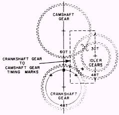
The drive mechanisms we have discussed so far have applied to 2-stroke cycle engines. We will now take a look at a gear train of a 4-stroke cycle engine (fig. 5-11). The gear train for the 4-stroke cycle engine is different from that of the 2-stroke cycle engine for two reasons. The first reason is that there is no provision for the driving of a blower since 4-stroke cycle diesel engines are either naturally aspirated or are turbocharged. Turbocharging units are exhaust-driven and require no mechanical drive. Another difference is the need for gear reduction in a 4-stroke cycle engine between the crankshaft and the camshaft. In a 4-stroke cycle engine, the camshaft speed must be exactly one-half the crankshaft speed. Remember, in a 4-stroke cycle engine, the crankshaft must rotate 720 for each power event per cylinder. The method by which the required 2:1 gear reduction is accomplished is by the use of one or more idler gears between the crankshaft gear and the camshaft gear. Refer to figure 5-11 as we explain how the 2:1 gear ratio is obtained in one type of engine. If the crankshaft were to revolve 360 degrees, it would move a total of 48 teeth. This movement is transmitted to the large idler gear, which will also revolve 360 degrees, or 48 teeth. As you can see in figure 5-11, a smaller idler gear with 30 teeth is mounted to the larger idler gear. This smaller gear is where the gear ratio starts to change. As the small idler gear revolves 360 degrees, or 30 teeth, it drives the camshaft gear 180 degrees, or 30 teeth. (The gear with the greater number of teeth will always revolve more slowly than the gear with the smaller number of teeth.) Thus, we now have the 2:1 ratio between the crankshaft and camshaft that is required for a 4-stroke cycle engine to operate. Now compare the gear train of the 4-stroke cycle engine in figure 5-11 to that of the 2-stroke cycle gear train in figures 5-1 and 5-5. You should be able to recognize the difference in these drive mechanisms. SUMMARY The drive mechanisms of an engine are those assemblies that transmit power for the operation of engine accessories and certain engine parts. The drive mechanisms may be a chain assembly, gear train, belts, or a combination of any of these parts. Some engines have only one drive mechanism, which is generally called the camshaft drive. Other engines may have a second major drive mechanism called the accessory drive. In most engines, each drive is generally identified by the name of the principal part or the accessory drive, such as blower drive, camshaft drive, and governor drive. The importance of these drive-transmitting devices is evident if you consider the function of the components to which power is transmitted. The VALVE-ACTUATING MECHANISMS control the fuel, intake air, exhaust gases, and starting air (when applicable) in the cylinders. The engine ACCESSORIES that are driven are those that circulate the cooling water and lubricating oil, supply air for scavenging and supercharging, supply fuel, and control engine speed. If you are unsure as to how these drive mechanisms function, we recommend you review the areas in which you are weak.
Figure 5-11.Gear train of a 4-stroke cycle engine showing gear ratio (Waukesha). |
||
|
||