| Tweet |

Custom Search
|
|
 
|
||
|
Dyer
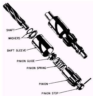
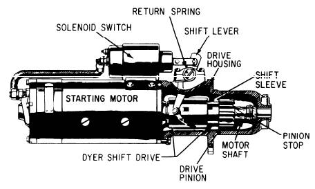
Drive Mechanism Figure 10-4 shows a starting motor assembly with a Dyer drive mechanism. Figure 10-5 shows an exploded view of the drive assembly. Refer to figures 10-4 and 10-5 as you read the discussion of the Dyer starter mechanism. The starting motor shown in figure 10-4, equipped with a Dyer shift drive, is operated through a solenoid starting shift and switch. The solenoid assembly is mounted on the starting motor and is connected to the battery and motor. Remote control starting is accomplished by a starter switch on the instrument panel which, upon being closed, energizes the starter solenoid. A heavy-duty plunger inside the solenoid is connected by linkage to the pinion shift lever that operates the Dyer drive. When the starter switch is closed, the battery energizes the coil of the solenoid switch which pulls the pinion gear into mesh with the ring gear on the flywheel. Continua-tion of the plunger movement closes the solenoid switch contacts, thereby removing the coil from the circuit and permitting the cranking motor to crank the engine. The Dyer drive consists of a splined section on the armature shaft, a shift sleeve, pinion, gear pinion guide, pinion stop, thrust washers, and springs. (See fig. 10-5.) The thrust washers furnish a thrust bearing for the shift sleeve when it is in the returned position. The springs aid in the lock operation and in the engagement action.
Figure 10-5.-Dyer shift drive mechanism. The entire drive is contained in the starting motor drive housing. The movement of the pinion is controlled by a shift lever which is connected directly to the shift sleeve. The Dyer drive provides a positive engagement of the cranking motor pinion gear with the engine
Figure 10-4.-A starting motor with a Dyer shift drive. flywheel before the cranking motor switch contacts are closed or the armature is rotated. This design prevents the pinion gear teeth from clashing with the flywheel ring gear. It also prevents the possibility of broken or burred teeth on either the ring gear or the drive pinion gear. The pinion gear is thrown out of mesh with the flywheel by the reversal of torque as the engine starts. The operation of the Dyer drive mechanism is similar to that of the Bendix drive. The four stages of operation are shown in figure 10-6. In view A, the mechanism is in the disengaged position. In view B, the starting switch has been energized and the solenoid is pulling its plunger in and is beginning to move the pinion gear toward the ring gear. In view C, the pinion gear has fully meshed with the ring gear, but the motor shaft has not begun to rotate. In view D, the motor shaft is rotating and the shift sleeve has returned to its original position. The drive pinion is moving the flywheel ring gear which cranks the engine. |
||
|
||