| Tweet |

Custom Search
|
|
 
|
||
|
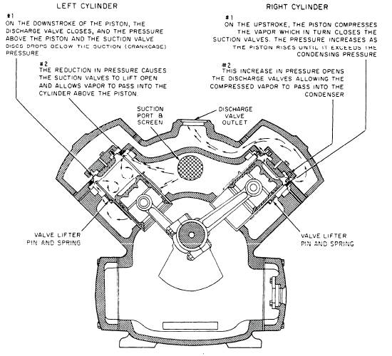
COMPRESSOR The compressor in a refrigeration system is essentially a pump. The compressor pumps heat uphill from the cold side to the hot side of the system. The compressor also keeps the refrigerant circulating and maintains the required pressure difference between the high-pressure and low-pressure sides of the system. The heat absorbed by the refrigerant in the evaporator must be removed before the refrigerant can again absorb latent heat. The only way the vaporized refrigerant can be made to give up the latent heat of vaporization it absorbed in the evaporator is by cooling it and causing it to condense. Because of the relatively high temperature of the available cooling medium, the only way to make the vapor condense is by first compressing it. When we raise the pressure, we also raise the temperature. By doing so, we have raised its condensing temperature, which allows us to use readily available seawater as a cooling medium in the condenser. Many different types of compressors are used in refrigeration systems. The designs of compressors vary depending on the application of the refrigerants used in the system. Figure 16-5 shows a motor-driven, single-acting, two-cylinder, reciprocating compressor, such as those com-monly used in naval refrigeration plants. Lubrication Compressors used in R-12 systems may be lubricated either by splash lubrication or by pressure lubrication. Splash lubrication, which depends on maintaining a fairly high oil level in the compressor crankcase, is usually satisfactory for smaller compressors. High-speed or large-capacity compressors use pressure lubrication systems. Shaft Seals Where the crankshaft extends through the crankcase, a crankshaft seal assembly prevents the refrigerant from escaping and air from entering the crankcase when the pressure in the crankcase is lower than the surrounding atmospheric pressure. There are several designs of seals used, such as the rotary seal, the stationary bellows, the rotating bellows, and the diaphragm.
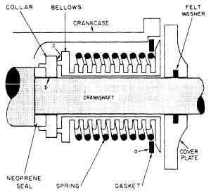
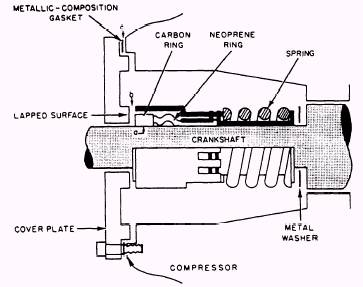
Figure 16-5.-Reciprocating compressor. The rotary seal, shown in figure 16-6, consists of a stationary cover plate and gasket and a rotating assembly, which includes a carbon ring, a neoprene seal, a compression spring, and compression washers. The seal-ing points are (a) between the crankshaft and the rotating carbon rings and sealed by a neoprene ring, (b) between the rotating carbon ring and the cover plate and sealed by lapped surfaces, and (c) between the cover plate and the crankcase and sealed by a metallic gasket. The seal is adjusted by adding or removing metal washers be-tween the crankshaft shoulder and the shaft seal compression spring. A stationary bellows seal is illustrated in figure 16-7. It consists of a bellows clamped to the compressor housing at one end to form a seal against a rotating shaft seal collar on the other end. The sealing points are (a) between the crankcase and the bellows and sealed by the cover plate gasket, (b) between the crankshaft and the shaft seal collar and sealed by a neoprene gasket, and (c) between the surface of the bellows nose and the surface of the seal collar and sealed by lapped surfaces. The stationary bellows seal is factory set for proper tension. You should not alter this seal.
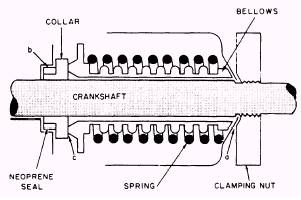
Figure 16-7.-Stationary bellows seal. The rotating bellows seal in figure 16-8 consists of a bellows clamped to the crankshaft at one end to form a seal against a stationary, removable shaft seal shoulder on the other end. The sealing points are located (a) between the
Figure 16-6.-Rotary seal.
Figure 16-8.-Rotating bellows seal. crankshaft and bellows and sealed by a shaft seal clamping nut, (b) between the removable shaft seal shoulder and the crankcase and sealed by a neoprene gasket, and (c) between the bellows nosepiece and the shaft seal collar and sealed by lapped surfaces. This seal is also factory set. The diaphragm seal in figure 16-9 con-sists of a diaphragm clamped to the crank-case at its outer circumference and to a fulcrum ring at its center. The shaft seal collar is locked to the shaft with the steel ball and, therefore, rotates with the shaft. All other parts in the seal assembly are stationary. The fulcrum ring forms a seal collar which is locked to the diaphragm. The sealing points are located (a) between the outer circumference of the diaphragm and the crankcase and sealed by a copper ring gasket, (b) between the fulcrum ring and the diaphragm-sealed at the factory and not to be broken, (c) between the ful-crum ring and the rotating shaft seal collar and sealed by lapped surfaces, and (d) be-tween the shaft seal collar and the crank-shaft shoulder and also sealed by lapped surfaces. You can adjust the tension in a diaphragm seal to obtain the specified deflection by adding or removing diaphragm-to-crankcase gaskets. For information on handling, clean-ing, and replacing shaft seal assemblies, con-sult the NAVSEA technical manual or the directions enclosed with the new seal. |
||
|
||