| Tweet |

Custom Search
|
|
 
|
||
|
AIRFLEX
CLUTCH AND GEAR ASSEMBLY On large diesel-propelled ships, the clutch, reverse gear, and reduction gear unit has to transmit an enormous amount of power. So that the weight and size of the mechanism can be main-tained as small as possible, special clutches have been designed for large diesel installations. One of these is the airflex clutch and gear assembly. The airflex clutch and gear assembly, shown in views A and B of figure 12-6, consists of two clutches-one for forward rotation (view A) and one for reverse rotation (view B). The basic principles of operation are illustrated in figure 12-7. The clutches are bolted to the engine
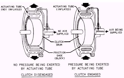
Figure 12-7.-Clutch operation. flywheel by a steel SPACER, so that they both rotate with the engine at all times at any engine speed. (See view A of fig. 12-6.) Each clutch has a flexible tube (gland) on the inner side of a steel shell. Before the tubes are inflated, they will rotate out of contact with the drums, which are keyed to the forward and reverse drive shafts. When air under pressure (100 psi) is forced into one of the tubes, the inside diameter of the clutch decreases. This causes the friction blocks on the inner tube surface to come in contact with the clutch drum, locking the drive shaft with the engine. (See figure 12-7.) |
||
|
||