| Tweet |

Custom Search
|
|
 
|
||
|
Airflex
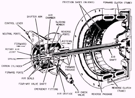
Clutch Control Mechanism The airflex clutch is controlled by an operating lever that works the air control housing, located at the afterend of the forward pinion shaft. The control mechanism, shown with the airflex clutches in figure 12-8, directs the air into the proper paths to inflate the clutch glands (tubes). The air shaft, which connects the control mechanism to the clutches, passes through the forward drive shaft. The supply air enters the control housing through the air check valve and must pass through the small air orifice. The restricted orifice delays the inflation of the clutch to be engaged during shifting from one direction of rotation to the other. The delay is necessary to allow the other clutch to be fully deflated and out of contact with its drum before the inflating clutch can make contact with its drum. The supply air goes to the rotary air joints in which a hollow carbon cylinder is held to the valve shaft by spring tension, preventing leakage between the stationary carbon seal and rotating air valve shaft. The air goes from the rotary joint to the four-way air valve. The sliding-sleeve assembly of the four-way valve can be shifted end-wise along the valve shaft by operation of the control lever. When the shifter arm on the control lever slides the valve assembly away from the engine, air is directed to the forward clutch. The four-way valve makes the connection between the air supply and the forward clutch. There are eight neutral ports, which connect the central air supply passage in the valve shaft with the sealed air chamber in the sliding member. In the neutral position of the four-way valve, as shown in figure 12-8, the air chamber is a dead end for the supply air. With the shifter arm in the forward position, the sliding member uncovers eight for-ward ports, which connect with the forward passages that conduct the air to the forward
Figure 12-8.-Airflex clutches and control valves. clutch. The air now flows through the neutral ports, air chamber, forward ports, and forward passages to inflate the forward clutch gland. As long as the shifter arm is in the forward position, the forward clutch will remain inflated, and the entire forward air system will remain at a pressure of 100 psi. At this point, let us assume that the bridge signals you to reverse the propeller. You should pull the operating lever back to the neutral position and hold it there for 2 or 3 seconds (as a safety factor). Then pull the lever to the reverse idling position and wait about 7 seconds, after which the reverse clutch is fully engaged. Then you can increase the reverse speed to whatever the bridge has ordered. Why was it necessary to pause at the neutral and the reverse idling positions? What has happened in the air control and clutch mechanism? When you shift to neutral, the for-ward ports are uncovered, and the compressed air from the forward clutch and passage vents to the atmosphere. When you deflate either clutch, the air is vented through eight ports approximately the same size as the air orifice, so that deflating either clutch actually requires 1 to 2 seconds. Pausing for 2 or 3 seconds at neutral allows enough time for the forward clutch to deflate and disengage before you start inflating the reverse clutch. When you shift to reverse idling, the air chamber comes over the eight reverse ports which open to the central reverse passage in the air shaft. The compressed air begins to inflate the reverse clutch immediately; the inflating air must pass through the single air orifice in the supply line, causing a delay of about 7 seconds to fully inflate a clutch. When the clutch is in the reverse idling position, wait until the reverse clutch is fully engaged before increasing the speed to prevent damaging the clutch (by slippage). It is impossible to have both clutches engaged at the same time. Unlike the transmissions previously dis-cussed, the gear units on diesel-propelled ships have a separate lubricating system. This type of lubricating system is shown in figure 12-9. The oil is picked up from the gear box by an electric-driven, gear-type lubricating oil pump and is sent through a strainer and cooler. After being cleaned and cooled, the oil is returned to the gear box to cool and lubricate the gears. In a twin installation, such as the one shown in figure 12-9, a separate pump is used for each unit and a standby pump is interconnected for emergency use. |
||
|
||