| Tweet |

Custom Search
|
|
 
|
||
|
Hydraulic
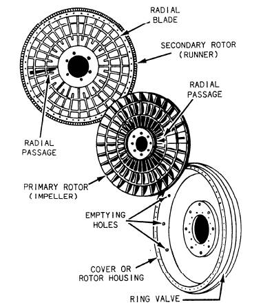
Coupling Assemblies The two rotors and the oil-sealing cover of a typical hydraulic coupling for a large propulsion unit is shown in figure 12-10. The primary rotor (impeller) is attached to the engine crankshaft. The secondary rotor (runner) is attached to the reduction gear pinion shaft. The cover is bolted to the secondary rotor and surrounds the primary rotor. Before proceeding with the assembly of the rotors and the shafts in the coupling housing, study the structure of the rotors themselves. Each rotor has a concave shape with radial partitions. A shallow trough is welded into the partitions around the inner surface of the rotor. The radial passages tunnel under this trough (as indicated by the arrows in fig. 12-10). When the coupling halves are assembled, the two rotors are placed facing each other to form
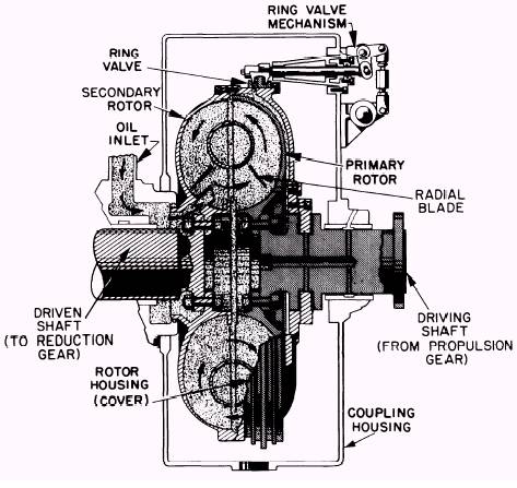
Figure 12-10.-Runner, impeller, and cover of hydraulic coupling. a series of circular chambers. (See fig. 12-11.) The rotors do not quite touch each other; the clearance between them is 1/4 to 5/8 inch, depending on the size of the coupling. The curved radial passages of the two rotors are opposite each other, so that the outer passages combine to make a circular passage except for the small gaps between the rotors. In the hydraulic coupling assembly shown in figure 12-11, the driving shaft is secured to the engine crankshaft and the driven shaft goes to the reduction gear box. The oil inlet admits oil directly to the rotor cavities, which become completely filled. The rotor housing is bolted to the secondary rotor and has an oil-sealed joint with the driving shaft. A ring valve, going entirely around the rotor housing, can be operated by the ring valve mechanism to open or close a series of emptying holes in the rotor housing. When the ring valve is opened, the oil will fly out the rotor housing into the coupling housing, draining the coupling completely in 2 or 3 seconds. Even when the ring valve is closed, some oil leaks out into the coupling housing, and additional oil enters through the inlet. From the coupling housing, the oil is drawn by a pump to a cooler, then sent back to the coupling. Another coupling assembly used in Navy ships is the hydraulic coupling with PISTON-TYPE quick-dumping valves. The operation of this coupling is similar to the one previously described. A series of piston valves are located around the periphery of the rotor housing. The piston valves are normally held in the closed position by springs. When air or oil pressure is admitted to the valves, the pistons are moved axially to uncover drain ports, allowing the coupling to empty. A hydraulic coupling with piston-type quick-dumping valves is used when extremely rapid declutching is not required. It offers greater simplicity and lower
Figure 12-11.-Hydraulic coupling assembly. cost than a hydraulic coupling with a ring valve mechanism. Another type of self-contained unit for certain diesel-engine drives is the SCOOP CONTROL COUPLING, shown in figure 12-12. In couplings of this type, the oil is picked up by one of two scoop tubes (one tube for each direction of rotation), mounted on the external manifold. Each scoop tube contains two passages: a smaller one (outermost), which handles the normal flow of oil for cooling and lubrication, and a larger one, which rapidly transfers oil from the reservoir directly to the working circuit. The scoop tubes are mechanically operated from the control station through a system of linkages. As one tube moves outward from the shaft center line and into the oil annulus, the other tube is being retracted. Four spring-loaded valves are mounted on the primary rotor. These valves, which are operated by centrifugal force, are arranged to open progressively as the speed of the primary rotor decreases. The arrangement provides the necessary oil flow for cooling as it is required. Quick-emptying piston valves are provided to empty the circuit rapidly when the scoop tube is withdrawn from contact with the rotating oil annulus. Under normal circulating conditions, oil fed into the collector ring passes into the piston valve control tubes. These tubes and connecting passages conduct oil to the outer end of the pistons. The centrifugal force of the oil in the control tube holds the piston against the valve port, thus sealing off the circuit. When the scoop tube is withdrawn from the oil annulus in the reservoir, the circulation of oil will be interrupted, and the oil in the control tubes will be discharged through the orifice in the outer end of the piston housing. This releases the pressure on the piston and allows it to move outward, thus opening the port for rapid discharge of oil. Resumption of oil flow from the scoop tube will fill the control tubes, and the pressure will move the piston to the closed position. |
||
|
||