| Tweet |

Custom Search
|
|
 
|
||
|
HELICAL
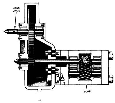
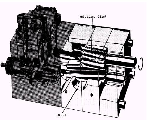
GEAR PUMP.-The helical gear pump (fig. 13-3) is still another modification
of the simple gear pump. Because of the helical gear design, the overlapping of
successive discharges from spaces between the teeth is even greater than it is
in the herringbone gear pump. The discharge flow is, accordingly, even
smoother. Since the discharge flow is smooth in the helical gear pump, the
gears can be designed with a small number of large teeth. This design allows
for increased capacity without sacrificing smoothness of flow. The pumping
gears in this type of pump are driven by a set of timing and driving gears,
which also function to maintain the required close clearances while preventing
actual metal-to-metal contact between the pumping gears. Metallic con-tact
between the teeth of the pumping gears would provide a tighter seal against
leakage; however, it would cause rapid wear of the teeth because foreign matter
in the pumped liquid would act like an abrasive on the contact surfaces. Roller bearings at both ends of the gear shafts maintain proper alignment, thereby minimizing the friction loss in the transmission of power. Stuffing boxes prevent leakage at the shafts. The helical gear pump can pump nonviscous liquids
Figure 13-2.-Herringbone gear pump.
Figure 13-3.-Helical gear pump. and light oils at high speed. At lower speed, it can pump heavy viscous materials. |
||
|
||