| Tweet |

Custom Search
|
|
 
|
||
|
SPECIAL-PURPOSE
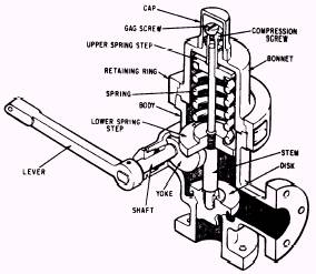
VALVES There are many types of automatic pressure control valves. Some of them merely provide an escape for excessive pressures. Others reduce or regulate fluid pressure. Relief Valves Relief valves are installed in piping systems to protect them from excessive pressure. These valves have an adjusting screw, a spring, and a disk. The force exerted on the disk by the spring sets the relieving pressure. Most relief valves simply open when the preset pressure is reached and close when the pressure drops slightly below the lifting pres-sure. Many relief valves will also have a lever so the valve can be opened by hand for test purposes. Figure 13-25 shows a relief valve of this type.
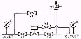
Figure 13-25.-Relief valve. Sentinel Valves Sentinel valves are simply small relief valves installed in some systems to warn of impending overpressurization. Sentinel valves do not relieve the pressure of the system. If the situation caus-ing the sentinel valve to lift is not corrected, a relief valve (if installed) will lift to protect the system or component. If a relief valve is not in-stalled, action must be taken quickly to secure the piece of equipment or system to reduce the pres-sure. Pressure-Reducing Valves Reducing valves are automatic valves that provide a steady pressure into a system that is at a lower pressure than the supply sys-tem. Reducing valves of one type or another are found in steam, air, lube oil, seawater, and other systems. A reducing valve can nor-mally be set for any desired downstream pres-sure within the design limits of the valve. Once the valve is set, the reduced pressure will be maintained. This is true regardless of changes in the supply pressure; however, the supply pressure must be at least as high as the reduced pressure desired. It is also true regardless of the amount of reduced pres-sure fluid that is used. Pressure-reducing valves for piping systems are usually installed in reducing stations, like the one shown in schematic form in figure 13-26. In addition to a pressure-reducing valve, a reducing station should contain at least four other valves. Two of these are stop valves,
Figure 13-26.-Pressure-reducing station. located in the inlet piping and outlet pip-ing for the reducing valve. These valves (V1 and V2) are shut to isolate the pressure-re-ducting valve from the piping system, in the event the valve needs repair. Some reduc-ing valves may also have a stop valve in the downstream sensing line (V3). There should be a bypass valve (V4), used for throttling service, to manually control downstream pres-sure when the reducing valve is inoperative. The bypass valve is normally shut. (NOTE: When a pressure-reducing station is lined up in the manual mode, the operator should use the indication on the outlet pressure gauge to adjust the bypass valve for the proper setting. The watch stander must check this setting periodically to ensure that the down-stream pressure setting is within the specified value.) Finally, there should be a relief valve (V5) to prevent overpressurization of the pip-ing system downstream of the reducing sta-tion in the event the reducing valve fails open (or the manual bypass valve is mis-adjusted). There are three basic designs of pressure-reducing valves in use. They are spring-loaded reducing valves, pneumatic-pressure-controlled (gas-loaded) reducing valves, and air-pilot-op-erated diaphragm-type reducing valves. There are many different styles within these three types. We will discuss a few of these varia-tions. |
 
|
|
|
||
|
|
Integrated Publishing, Inc. - A (SDVOSB) Service Disabled Veteran Owned Small Business
|