| Tweet |

Custom Search
|
|
 
|
||
|
COMPONENTS
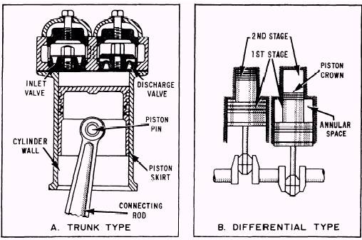
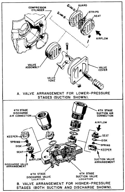
AND SYSTEMS Reciprocating air compressors consist of a system of connecting rods, a crankshaft, and a flywheel. These parts transmit power developed by the driving unit to the pistons as well as to the lubrication systems, cool-ing systems, control systems, and unloading systems. Compressing Element The compressing element of a reciprocating air compressor consists of the cylinders, pistons, and air valves. CYLINDERS.-The design of the cylin-ders depends mostly upon the number of stages of compression required to produce the maximum discharge pressure. Several common cylinder arrangements for low- and medium-pressure air compressors are shown in view A of figure 14-3. Several arrange-ments for the cylinders and pistons of high-pressure air compressors are shown in view B of figure 14-3. The stages are numbered 1 through 4. Notice that a three-stage ar-rangement and a four-stage arrangement are both shown. The basic stage arrangement is similar for the five- and six-stage compres-sors. PISTONS.-The pistons may be either of two types: trunk or differential. (See fig. 14-5.) TRUNK PISTONS are driven directly by the connecting rods (view A). The upper end of a connecting rod is fitted directly to the piston by a wrist pin. This design produces a tendency for the piston to develop a side pressure against the cylinder walls. For the side pressure to be distributed over a wide area of the cylinder walls or liners, pistons with long skirts are used. The design of the trunk piston helps minimize cylinder wall wear. DIFFERENTIAL PISTONS, shown in view B of figure 14-5, are modified trunk pistons with two or more different diameters. These pistons are fitted into special cylinders, arranged so that more than one stage of compression is achieved by a single upward stroke of the piston. The compression for one stage takes place over the piston crown; compression for the other stage(s) takes place in the annular space between the large and small diameters of the piston. VALVES.-The valves are made of special steel and come in a number of different types. The opening and closing of the valves is caused by the difference between (1) the pressure of the air in the cylinder and (2) the pressure of the external air on the intake valve or the pressure of the discharged air on the discharge valve. Two types of valves commonly used in high-pressure air compressors are shown in figure 14-6. The strip- or feather-type valve is shown in view A. It is used for the suction and discharge valves of the lower-pressure stages (1 and 2). The valve shown in view A is a suction valve; the discharge valve assembly (not shown) is identical except that the positions of the valve seat and the guard are reversed. At rest, the thin strips lie flat against the seat. They cover the slots and form a seal when pressure is applied to the guard side of the valve. The following action works in either a suction or a discharge operation (depending on the valve service). As soon as pressure on the seat side of the valve exceeds the pressure on the guard side, the strips flex against the contoured recesses in the guard. As soon as the pressure equalizes or reverses, the strips unflex and return to their original position, flat against the seat. The disk-type valve in view B of figure 14-6 is used for the suction and discharge valves of the higher-pressure stages (3 and 4). The fourth stage assembly is shown in view B. The valves shown are the spring-loaded, dished-disk type. At rest, the disk is held against the seat by the spring. It forms a seal when pressure is applied to the keeper
Figure 14-5.-Air compressor pistons.
Figure 14-6.-High-pressure air compressor valves. side of the valve. The following action works in either a suction or a discharge operation (depending on the valve service). When the pressure on the seat side of the valve exceeds the pressure on the keeper side, the disk lifts against the stop in the keeper. This action compresses the spring and permits air to pass through the seat, around the disk, and through the openings in the sides of the keeper. As soon as the pressure equalizes or reverses, the spring forces the disk back onto the seat. |
||
|
||