| Tweet |

Custom Search
|
|
 
|
||
|
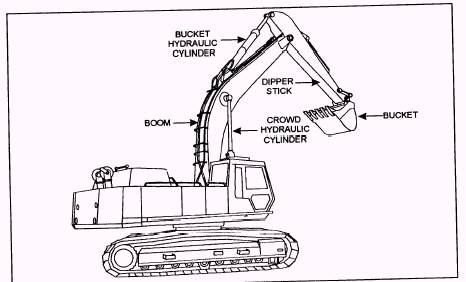
Truck Mounted The revolving unit is carried on a turntable fastened to a truck chassis. Some units may have an engine mounted in the revolving unit to provide power for the upper unit controls and a engine mounted in the truck to be used for traveling. Some truck-mounted units may only have one engine used to power both the revolving unit and truck. The truck-mounted excavator can ordinary swing in a full 360-degree rotation, but with most attachments, it can work through only 270 degrees because of interference presented by the cab and the truck front. NOTE: A common rule of thumb is to never swing or perform work with a revolving unit over the cab or front of the truck. Some truck-mounted units are equipped with outriggers mounted on the rear that increase the stability of the truck. These outriggers are normally hydraulically actuated and controlled from the cab of the truck and provide a much larger and more rigid base than tires. The advantage of truck mounting over track mounting is its capacity for rapid movement from one job to another. The boom can be placed easily in the boom rest for traveling and then driven down the road at 25 to 35 miles per hour. This is better than the slow laborious job of trailer loading, securing, hauling, and unloading a track-mounted excavator. The truck-mounted excavator suffers from a lack of maneuverability compared to the track mounting, because it requires a large area to turn around or to sidestep. Additionally, an important weakness is the ease with which it can get stuck. Constant care must be exercised to keep away from soft ground during or after it rains. Also, tire damage can occur when working in garbage dumps or a rock quarry. Self-Propelled Wheel Mounted The self-propelled single-engine unit has a tworange transmission, enabling it to travel between 3 and 28 miles per hour. Maneuverability on the job is subject to the same limitations as the truck mounted, except the short wheelbase, and in some models, four-wheel steering allows it in tighter places. The self-propelled model has front axle oscillation lock levers. These levers are used to lock out the front axle from oscillating up or down, holding the axle rigid and level with the main chassis. The lock lever is used to help stabilize the excavator when working over the side. NOTE: When reading, make sure the oscillation lock levers are up in the oscillate position, allowing the axle freedom to oscillate up or down. The self-propelled model has a set of outriggers used to increase the stability of the unit. These outriggers are hydraulically actuated and are controlled from the cab and provide a much larger and more rigid base when the revolving unit is placed in the working position. When traveling, always check the travel route for weight, height, and width limits, make sure the boom and steering selector are placed in the travel position, and the swing brake is engaged. Do not travel with the boom over the side of the excavator, and if traveling off of the road, do not travel faster than 5 miles per hour. NOTE: After 2 hours of highway travel or every 50 miles, whichever occurs first, stop the machine to let the tires cool for 1/2 hour. Heat damages the tires and can cause tire failure. ATTACHMENTS All hydraulic excavator attachments are made of three strong structural members, such as the boom, the dipper stick, and the bucket (fig. 9-58). The structural members are hinged to each other, and the boom is hinged to the revolving unit. Movement at each hinge is controlled by two-way hydraulic cylinders. Boom The boom is normally concave towards the ground that allows space to pull the bucket closer to the excavator, permits deeper digging without interference from the travel unit, and enables the operator to see past it more easily when it is raised. There are two holes for connecting the boom cylinder rod eye to the boom (fig. 9-59). The top hole is for maximum digging depth, and the bottom hole is for maximum dump height. Be sure to read the operator's manual for instructions on the boom height-depth adjustment. The outer end of the boom is usually prolonged into a two-piece bracket, in which the dipper stick is held by a heavy hinge pin or pins. Dipper Stick The dipper stick is usually one-piece, but some models may hydraulically extend and retract by a telescoping boom. The dipper stick hydraulic crowd cylinder is either connected on the top or on the bottom of the dipper, and the bucket and bucket dump arms are connected at the end. If the dipper stick hydraulic crowd cylinder is mounted on the top, extending the cylinder forces the bucket in towards the machine, known as "crowding." Retracting the cylinder forces the bucket outward, known as "extending." When the cylinder is mounted underneath the boom, retracting the cylinder crowds the dipper stick, and extending the cylinder extends the dipper stick.
Figure 9-58.-Hydraulic excavator structural members.
Figure 9-59.-Boom depth-height adjustment. WARNING When working off the rear of an excavator that has the dipper stick hydraulic cylinder mounted on the bottom, in deep digging, caution must be taken to keep the dipper stick hydraulic cylinder far enough from the excavator to allow proper clearance when swinging. The bucket cylinder is hinged to the top or front side of the dipper stick. The hydraulic cylinder rod is connected to the bucket dump arms that are hinged to the dipper stick. |
||
|
||