| Tweet |

Custom Search
|
|
 
|
||
|
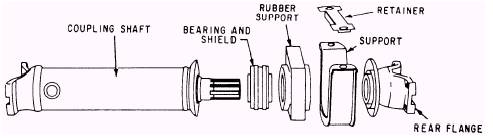
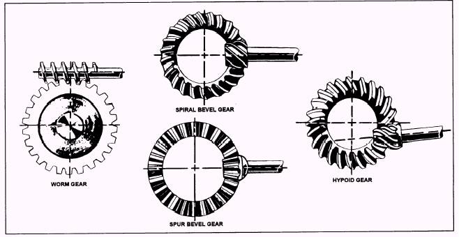
CENTER SUPPORT BEARINGS When two or more propeller shafts are connected together in tandem, their alignment is maintained by a rubber-bushed center support bearing, secured to a cross member of the frame. A typical center support bearing assembly is shown in figure 2-14. The standard bearing is prelubricated and sealed and requires no further lubrication; however, some support bearings on heavy-duty vehicles have lubrication fittings. The first indication of support bearing failure is excessive chassis vibration at low speed caused by the bearing turning with the shaft in the rubber support. A final drive transmits the power delivered from the propeller shaft to the drive wheels or to sprockets equipped on tracklaying equipment. Because it is located in the rear axle housing, the final drive is usually identified as a part of the rear axle assembly. The final drive consists of two gears, called the ring gear and pinion. These are beveled gears, and they may be worm, spiral, spur, or hypoid, as shown in figure 2-15. The function of the final drive is to change by 90 degrees the direction of the power transmitted through the propeller shaft to the driving axles. It also provides a fixed reduction between the speed of the propeller shaft and the axles driving the wheels. In passenger
Figure 2-14.-Center support bearing.
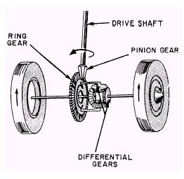
Figure 2-15.-Gears used in final drives. cars, this reduction varies between 3 to 1 and 5 to 1. In trucks, it can vary from 5 to 1 to as much as 11 to 1. The gear ratio of a final drive with bevel gears is frond by dividing the number of teeth on the driven or ring gear by the number of teeth on the pinion. In a worm gear final drive, the gear ratio is found by counting the number of revolutions of the worm gear for one revolution of the driven gear. Most final drives are gear type. Hypoid differential gears permit a lower body design. They permit the bevel-driven pinion to be placed below the center of the ring gear, thereby lowering the propeller shaft, as shown in figure 2-15. Worm gears allow a larger speed reduction and are sometimes used on large trucks. Spiral bevel gears are similar to hypoid gears and are used in both passenger cars and trucks to replace spur gears that are too noisy. DIFFERENTIALS Another important unit in the power train is the differential, which is a type of final drive. As shown in figure 2-16, the differential is located between the axles and permits one axle shaft to turn at a different speed from that of the other. At the same time, the differential transmits power from the transmission/transfer case to both axle shafts. The variation in axle shaft speed is
Figure 2-16.-Differential operation. necessary when the vehicle turns a corner or travels over uneven ground. As a vehicle travels around a curve, the outer wheel must travel faster and further than the inner wheel. Without the differential, one rear wheel would be forced to skid when turns are made, resulting in excessive tire wear as well as making the vehicle more difficult to control. Some trucks have a differential lock to keep one wheel from spinning. This is a simple dog clutch, part of the vehicle weight but does not drive the wheels. The wheels rotate on the ends of the dead axle. On rear wheel drive passenger cars, the front axle is a dead axle, and the rear axle is a live axle. In four-wheel drive vehicles, both front and rear axles are live axles, and in six-wheel drive vehicles, all three axles are live. Axles are classified as either live or dead. The live axle is used to transmit power. The dead axle supports controlled manually or automatically. The differential lock locks one axle shaft to the differential case and bevel drive gear, forming a rigid connection between the two axle shafts that makes both wheels rotate at the same speed. |
 
|
|
|
||