| Tweet |

Custom Search
|
|
 
|
||
|
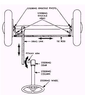
CHAPTER 3 CHASSIS SYSTEMS Chassis systems provides operators with a means of controlling the direction the equipment travels and allows travel over uneven terrain by controlling the amount of shock reaching the passengers or cargo. This chapter covers the basic principles of steering systems, suspension systems, tires, and brake systems. STEERING SYSTEMS Automotive steering mechanisms are classified as either manual or power. In both types, the arrangement and function of the linkage are similar. The main difference is that manual steering requires more effort for you to steer the vehicle. Some construction equipment has articulated steering which is powered by the equipment hydraulic system. STEERING MECHANISMS All steering mechanisms have the same basic parts (fig. 3-1). The steering linkage ties the front wheels together and connects them to the steering gear case at
Figure 3-1.-Steering linkage assembly. the lower end of the steering column which, in turn, connects the gear case to the steering wheel. The arms and rods of the steering linkage have ball ends or ball-and-socket ends to provide a swivel connection between them. These joined ends have grease fittings, dust seals or boots, and many of them have end-play adjustment devices. These joints and devices must be adjusted and lubricated regularly. The arms, rods, and joints of steering linkage in your equipment may be arranged differently from those shown in figure 3-1, but you will find them in the same general location in the front and underneath the vehicle. The tie rod is usually behind the axle and keeps the front wheels in proper alignment. The tie rod is divided into two lengths and is connected to the steering gear near the center of the vehicle to provide for easier steering and maximum leverage. The drag link between the steering arm and the pitman arm may be long or short, depending on the installation. The pitman arm is splined to the shaft extending from the steering gear case. It moves in an arc with its position, depending on which direction the steering wheel is turned. The arm is vertical when the front wheels are straight ahead. Therefore, the length of the drag link is determined by the distance between the steering arm and the vertical position of the pitman arm. Unlike the tie rods, the length of the drag link is fixed. Part of your prestart and operator maintenance responsibilities is to check and service the steering linkage lubrication. One example is the connecting joints between the links that contain bushings. Additionally, when a vehicle is equipped with manually operated steering, check the steering gear housing for lubrication, and, if needed, add the recommended manufacturer's gear lubricant. If the vehicle is equipped with power steering, check the belt tension because improper tension can cause low oil pressure and hard steering. Check the fluid level. If the fluid level is low, add fluid to bring it up to the recommended level and only use the recommended power steering fluid. Also, if the level is low, there may be a leak; therefore, check hose and power steering connections for signs of leaks. The connections may only need tightening to eliminate leaks; however, leakage may occur at various points in the power steering unit if the seals are defective. Document conditions and report them to the maintenance shop for replacement of any defective seal. The types of steering troubles that develop in vehicle operations that should be documented and turned in for repair are as follows: l Excessive play in the steering system l Hard steering l Vehicle wanders l Vehicle pulls to one side when braking Front-wheel shimmy Front-wheel tramps (high-speed shimmy) l Steering kickback l Tires squeal on turns Improper tire wear l Unusual noises These problems must be documented and turned in for repairs. |
 
|
|
|
||