| Tweet |

Custom Search
|
|
 
|
||
|
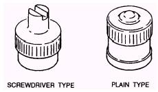
Valves For speed and convenience during inflation, valve stems should be readily accessible. They should be properly centered in the valve holes and slots to prevent scraping against the brake drums. They should be placed so the valves extend through the wheels. Valves on the inside duals should point away from the vehicle, and the valves on the outside duals should point toward the vehicle. On dual wheels, the valve of the outside dual is placed 180 degrees from the inside valve for speed and convenience in checking pressures and inflation. With this arrangement, the locations of the valves are always known even when you are checking them in the dark. Spare tires should be mounted so that the valve is accessible for checking and inflating. VALVE CORES.- The valve core (fig. 3-12) is that part of the valve that is screwed into the valve stem and permits air, under pressure, to enter, but prevents it from escaping. Two types of valve cores and two sizes of each type are in use today. The two types are the visible spring type and the concealed spring type. The two types are interchangeable. Two sizes are provided for the standard bore and the large bore valve stems. The core shell has a rubber washer that provides an airtight seal against the tapered seat inside the stem. Directly below the shell is a cup that contains a rubber seat, which, in the closed position, is forced against the bottom of the shell, forming an airtight seal. The pin on top of the valve core, when pushed down, forces the cup away from the shell, permitting air to flow. VALVE CAPS.- The valve cap (fig. 3-13) is also a component part of the valve and is screwed onto the end of the stem, providing a second airtight seal. The cap also protects the threads on the end of the stem and
Figure 3-13.-Valve caps.
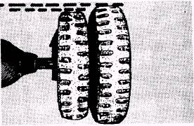
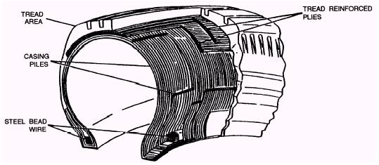
Figure 3-14.-Mismatched tires keeps dirt and moisture out of the valve body. The screwdriver cap has a forked tip that may be used to install or remove the valve core. The plain cap generally is used on rubber-covered valves and has a skirt that contacts the rubber covering on the valve stem. Both caps are interchangeable with each other. Part of your prestart operation is making sure that all valve stems have valve caps. For longer tire life and more efficient performance, dual tires and tires on all-wheel drive vehicles must be of the same size, tread design, and tread wear. Improperly matched tires cause rapid uneven wear and can also cause transfer case and differential failures. Accurate matching of tires is necessary, because tires on axle-drive vehicles rotate at the same speed when all axles are engaged. Dual wheels turn at the same speed, because they are locked together which means that tires on all driving wheels must be of the same circumference and diameter. When one tire of a pair of duals is worn considerably more than the other, the tire cannot carry its proper share of the load and will scrub the road (fig. 3-14). The result is uneven and rapid wear on both tires and/or tire failure. Tires should be used in sets. Mixing different types (bias ply, fiber glass belted, radial ply) must be avoided. Snow tires should be of the same size and type of construction as the front tires. Radial-ply tires should always be used in sets. NOTE: Under no circumstances should radial-ply tires be mixed with bias-ply tires, together or on the same axle. The problems encountered when mixing tires on a vehicle are loss of steering control, inadequate vehicle handling, and potential mechanical damage. These problems vary depending on the stability of the tires used, differences in dimensions, differences in air pressure, and other operating conditions. RADIAL-PLY TIRES.- Radial-ply tires (fig. 3-15) are constructed with casing plies perpendicular to the tread direction, with several layers of tread-reinforcing plies (steel or fabric) just under the tread area. This construction permits flexing of the tire with a minimum of tread distortion, better traction, and a softer ride.
Figure 3-15.-Radial-ply tire construction.
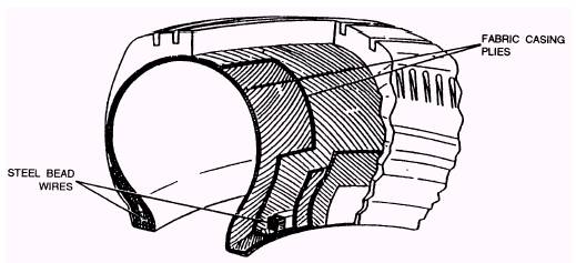
Figure 3-16.-Bias-ply tire construction. BIAS-PLY TIRES.- Bias-ply tires (fig. 3-16) are constructed of rayon, nylon, or polyester casing plies in a crisscross pattern wrapped around steel bead wires. These bead wires prevent the tire from opening up and separating from the rim at high speeds. The casing plies give the tire its shape.
Figure 3-17.-Results of mechanical irregularities. |
 
|
|
|
||