| Tweet |

Custom Search
|
|
 
|
||
|
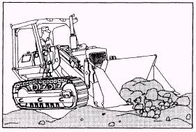
When operating a loader equipped with a skid bucket, keep the engine speed at full throttle and operate in the first or second gear transmission range. Use second and third gear for traveling. Start all jobs from nearly level ground if possible. When necessary, level an area large enough to provide
Figure 9-9.-Up-and-down pitching of a loader on irregularterrain. sufficient working space for the loader. This step prevents up-and-down pitching of the loader (fig. 9-9) and results in a smoother digging operation. Track and wheel spinning should be avoided, because loader tires are expensive and excessive spinning of the tires while loading causes premature wear and tear. Additionally, it converts a smooth working area into ruts that pitch and tilt the loader. A smooth working area is safer and more comfortable. It also puts less wear and tear on the machine and yourself; therefore, production is increased. Cross ditches, ridges, rocks, or logs slowly and, if possible, at an angle. This procedure slows the fall, lessens the danger of upsetting the loader, and reduces the jolt of the fall that can harm both the operator and the loader. A uniform system of hand signals must be used in all front-end loader operations. While the authority for giving signals must be assigned to only one person under normal working conditions, the responsibility for giving an emergency stop signal belongs to anyone in the vicinity who believes such a signal is necessary. The person giving the signals must be clearly visible to the operator at all times. Hand signals used in front-end loader operations are shown in appendix IV. NOTE: You must recognize and understand these signals when operating equipment. Additionally, you must also be able to give them when called on to act as a signalman during any equipment operation. Automatic Bucket Leveler Most 515 B series dresser rubber-tired front-end loaders used in the NCF have an automatic bucket
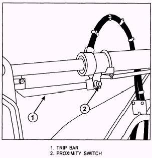
Figure 9-10.-Automatic bucket leveler. leveler located on the underside of the bucket cylinder (fig. 9-10). The automatic bucket leveler is preset to stop the bucket in a horizontal or digging position. A trip bar (1) is attached to and moves with the cylinder rod. The proximity switch (2) creates a magnetic field circuit that is completed by the proximity of the trip bar within the magnetic field. Once the bucket is dumped, place the bucket lever in the bucket "rollback" position. When the bucket reaches its preset position, the trip bar moves out of the magnetic field circuit created by the proximity switch and automatically stops. Then the bucket control lever returns to the "hold" position. NOTE: Refer to the manufacturer operator's manual when the automatic bucket leveler needs adjustment. |
 
|
|
|
||