| Tweet |

Custom Search
|
|
 
|
||
|
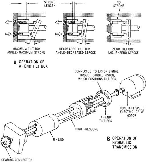
ELECTROHYDRAULIC DRIVE MACHINERY Hydraulic units drive or control steering gears, windlasses, winches, capstans, airplane cranes, ammunition hoists, and distant control valves. In this part of the chapter, you will learn about some of the hydraulic units that will concern you. The electrohydraulic type of drive operates several different kinds of machinery better than other types of drives. Here are some of the advantages of electrohydraulic machinery. Tubing, which can readily transmit fluids around corners, conducts the liquid which transmits the force. Tubing requires very little space. The machinery operates at variable speeds. Operating speed can be closely controlled from minimum to maximum limits. The controls can be shifted from no load to full load rapidly without damage to machinery. ELECTROHYDRAULIC SPEED GEAR. An electrohydraulic speed gear is frequently used in electrohydraulic applications. Different variations of the basic design are used for specific applications, but the operating principles remain the same. Basically, the unit consists of an electric motor-driven hydraulic pump (A-end) and a hydraulic motor (B-end). The B-end (fig 10-37) is already on stroke and is rotated by the hydraulic force of the oil acting on the pistons. Movement of the pistons' A-end is controlled by a tilt box (also called a swash plate) in which the socket ring is mounted, as shown in part A of figure 10-37. The length of piston movement, one way or the other, is controlled by movement of the tilt box and by the amount of angle at which the tilt box is placed. The length of the piston movement controls the amount of fluid flow. When the drive motor is energized, the A-end is always in motion. However, with the tilt box in a neutral or vertical position, there is no reciprocating motion of the pistons. Therefore, no oil is pumped to the B-end. Any movement of the tilt box, no matter how slight, causes pumping action to start. This causes immediate action in the B-end because force is transmitted by the hydraulic fluid. When you need reciprocating motion, such as in a steering gear, the B-end is replaced by a piston or ram. The force of the hydraulic fluid causes the movement of the piston or ram. The tilt box in the A-end is controlled locally (as on the anchor windlass) or remotely (as on the steering gear). ELECTROHYDRAULIC STEERING GEAR The steering gear transmits power from the steering engine to the rudder stock. The steering gear frequently includes the driving engine and the transmitting mechanism. Many different designs of steering gear are in use, and they all operate on the same principle. One type of
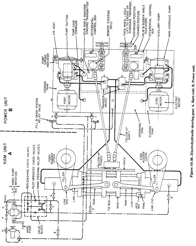
Figure 10-37.-Electrohydraulic speed gear. electrohydraulic steering gear is shown in figure 10-38. It consists essentially of a ram unit and a power unit. Ram Unit The ram unit (view A) is mounted athwartship and consists of a single ram operated by opposed cylinders. The ram is connected by links to the tillers of the twin rudders. When oil pressure is applied to one end of the operating cylinder, the ram moves, causing each rudder to move along with it. Oil from the opposite end of the cylinder is returned to the suction side of the main hydraulic pump in the power unit. Power Unit The power unit (view B) consists of two independent pumping systems. Two systems are used for reliability. One pump can be operated while the other is on standby. Each pumping system consists of a variable-delivery, axial-piston main pump and a vane-type auxiliary pump. Both are driven by a single electric motor through a flexible coupling. Each system also includes a transfer valve with operating gear, relief valves, a differential control box, and trick wheels. The whole unit is mounted on a bedplate that serves as the top of an oil reservoir. Steering power is taken from either of the two independent pumping systems. The pumps of the power unit are connected to the ram cylinders by high-pressure piping. The two transfer valves are placed in the piping system to allow for the lineup of one pump to the ram cylinders with the other pump isolated. A hand lever and mechanical link (not shown) are connected to the two transfer valves so that
both valves are operated together. This allows rapid shifting from the on-service pumping unit to the standby unit; it prevents lining up both pumps to the ram at the same time. The hand lever is usually located between the trick wheels. It has three positions marked P, N, and S. P denotes the port pump is connected to the ram; N denotes neutral (neither pump connected to the ram); and S denotes the starboard pump is connected to the ram. Also, the hand lever is usually connected to motor switches. This lets the operator connect the selected pump to the ram and start the pump drive motor in one quick operation. In most ships this valve is electrically controlled by the motor controller and by pressure switches. Principles of Operation The on-service hydraulic pump is running at all times and is a constant-speed pump. Unless steering is actually taking place, the tilt box of the main hydraulic pump is at zero stroke, and no oil is being moved within the main system. The auxiliary pump provides control oil and supercharge flows for the system. To understand the operation of the pump, let's assume that a steering order signal comes into the differential control box. It can come from either the remote steering system in the ship's wheelhouse or the trick wheel. The control box mechanically positions the tilt box of the main hydraulic pump to the required angle and position. NOTE: Remember that direction of fluid and flow may be in either direction in a hydraulic speed gear. It depends on which way the tilt box is angled. For this reason, the constant-speed, unidirectional motor can be used to drive the main hydraulic pump. The pump will still have the capability to drive the ram in either direction. With the main hydraulic pump now pumping fluid into one of the ram cylinders, the ram moves, moving the rudders. A rack and gear are attached to the rudder yoke between the rudder links. As the ram and the rudder move, the rack gear moves, driving the follow-up pinion gear. The pinions drive follow-up shafts that feed into the differential box. This feedback or servo system tells the differential control box when the steering operation is complete. As the ordered rudder angle is approached, the differential control box begins realigning the tilt box of the main hydraulic pump. By the time the desired rudder angle is reached, the tilt box is at zero stroke. This means that the ordered signal (from the pilot house or trick wheel) and the actual signal (from the follow-up shafts) are the same. If either of these change, the differential control box reacts accordingly; the main hydraulic unit pumps oil to one end or the other of the ram. The trick wheels provide local-hydraulic control of the steering system of the remote steering system fails. A hand pump and associated service lines are also provided for local-manual operation of the ram if both hydraulic pump units fail. Operation and Maintenance The Machinist's Mate watch stander usually operates the steering equipment only in abnormal and emergency situations. For this reason, you should be thoroughly familiar with all emergency procedures, such as local-hydraulic steering with the trick wheel and local-manual steering with the hand pump. Operating instructions and system diagrams are normally posted near the steering gear. The diagrams describe the various procedures and lineups for operation of the steering gear. Be sure that the standby equipment is ready for instant use. General maintenance of the steering gear requires that you clean, inspect, and lubricate the mechanical parts and maintain the hydraulic oil at the proper level and purity. The Planned Maintenance System (PMS) lists the individual requirements for the equipment. The electricians maintain the electrical portion of the steering system, including the control system. |
 
|
|
|
||