| Tweet |

Custom Search
|
|
 
|
||
|
BELLOWS GAUGE A bellows gauge contains an elastic element that is a convoluted unit that expands and contracts axially with changes in pressure. The pressure to be measured can be applied to the outside or inside of the bellows. However, in practice, most bellows measuring devices have the pressure applied to the outside of the bellows (fig.11-7) . Like Bourdon-tube elements, the elastic elements in bellows gauges are made of brass, phosphor bronze, stainless steel, beryllium-copper, or other metal that is suitable for the intended purpose of the gauge. Most bellows gauges are spring-loaded; that is, a spring opposes the bellows, thus preventing full expansion of the bellows. Limiting the expansion of the bellows in this way protects the bellows and prolongs its life. In a spring-loaded bellows element, the deflection is the result of the force acting on the bellows and the opposing force of the spring. Although some bellows instruments can be designed for measuring pressures up to 800 psig, their primary application aboard ship is in the measurement of low pressures or small pressure differentials.
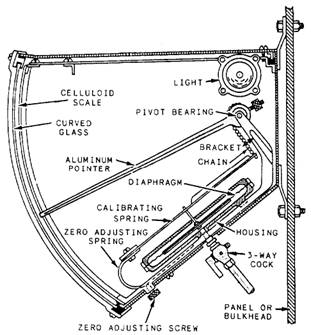
Figure 11-8.-Diaphragm gauge. Many differential pressure gauges are of the bellows type. In some designs, one pressure is applied to the inside of the bellows, and the other pressure is applied to the outside. In other designs, a differential pressure reading is obtained by opposing two bellows in a single case. Bellows elements are used in various applications where the pressure-sensitive device must be powerful enough to operate not only the indicating pointer but also some type of recording device. DIAPHRAGM GAUGES Diaphragm gauges are very sensitive and give reliable indication of small differences in pressure. Diaphragm gauges are generally used to measure air pressure in the space between the inner and outer boiler casings. Figure 11-8 shows the indicating mechanism of a diaphragm gauge. This mechanism consists of a tough, pliable, neoprene rubber membrane connected to a metal spring that is attached by a simple linkage system to the gauge pointer. One side of the diaphragm is exposed to the pressure being measured, while the other side is exposed to the atmosphere. When pressure is applied to the diaphragm, it moves and, through a linkage system, moves the pointer to a higher reading on the dial. When the
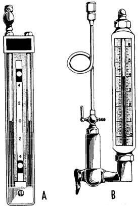
Figure 11-9.-A. Standard U-tube manometer. B. Single-tube manometer. pressure is lowered, the diaphragm moves the pointer back toward the zero point. |
||
|
||