| Tweet |

Custom Search
|
|
 
|
||
|
TANK LEVEL INDICATORS Many tank levels are monitored to provide the exact liquid level contained. For example, fuel tanks are monitored to make sure they do not overflow. They are also monitored to let the engineer officer know the amount of fuel aboard ship. The sensors used to monitor these levels are TLIs. Each of the level-monitored tanks contains a level transmitter. A typical transmitter section contains a voltage divider resistor network that extends the length of the section. Magnetic reed switches are tapped at 1-inch intervals along the resistor network. The reed switches are sequentially connected through series resistors to a common conductor. This network is enclosed in a stem that is mounted vertically in the tank. A float containing bar magnets rides up and down the stem as the liquid level changes. In many tanks, you may have to use more than one transmitter section to measure the full range. The physical arrangement of some tanks makes this necessary. When multiple sections are used, they are electrically connected as one continuous divider network. Two types of floats are used. In noncompensated tanks, the float is designed to float at the surface of the fuel or JP-5. For seawater-compensated tanks, the float is designed to stay at the seawater/fuel interface. CONTACT LEVEL SENSORS Many times, you do not have to know the exact level of a tank until it reaches a preset level. When this type of indication is needed, you can use a contact or float switch. Two types of float level switches are used on gas turbine ships. One type of float level switch is the lever-activated switch, which is activated by a horizontal lever attached to a float. The float on this switch is located inside the tank. When the liquid level reaches a preset point, the lever activates the switch. The other type of level switch has a mag-net-equipped float that slides on a vertical stem. The stem contains a hermetically sealed, reed switch. The float moves up and down the stem with the liquid level.
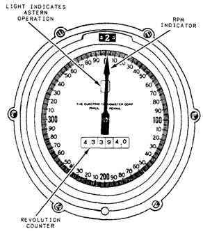
Figure 11-23.-Revolution counter. It magnetically opens or closes the reed switch as the float passes over it. Figure 11-22 shows the construction of the magnetically operated float switch. Magnetic float switches may be constructed with more than one float on a stem. Magnetic float switches can be installed to detect multiple levels in the same tank; and this type of switch can activate a high- and low-level alarm. REVOLUTION COUNTERS AND INDICATORS Measurements of rotational speed are necessary for the proper operation of pumps, forced-draft blowers, main engines, and other components of the engineering plants. Various types of instruments are used to measure equipment revolutions per minute (rpm) and count the number of revolutions a shaft makes. |
 
|
|
|
||