| Tweet |

Custom Search
|
|
 
|
||
|
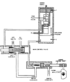
Control For the purpose of this text, control constitutes the relationship between the stroke control shaft and the tilting box. The stroke control shaft is one of the piston rods of a double-acting piston-type actuating cylinder. This actuating cylinder and its direct means of control are referred to as the main cylinder assembly (fig. 12-6). It is the link between the hydraulic followup system and the power drive itself.In hand control, the tilting box is mechanically positioned by gearing from the handwheel through the A-end control unit. In local and automatic control, the tilting box is positioned by the stroke control shaft. As shown in figure 12-6, the extended end of the control shaft is connected to the tilting box. Movement of the shaft will pivot the tilting box one way or the other; which, in turn, controls the output of the A-end of the transmission. The other end of the shaft is attached to the main piston. A shorter shaft is attached to the opposite side of the piston. This shaft is also smaller in diameter. Thus the working area of the left side of the piston is twice that of the area of the right side, as it appears in figure 12-6.
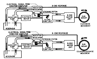
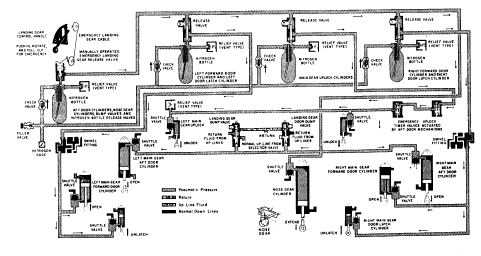
Figure 126.Main cylinder assembly. Intermediate high-pressure fluid (IHP) is transmitted to the left side of the piston, while high-pressure hydraulic fluid (HPC) is transmitted to the right side. The HPC is held constant at 1000 psi. Since the area of the piston upon which HPC acts is exactly one-half the area upon which IHP acts, the main piston is maintained in a fixed position when IHP is one-half HPC (500 psi). Whenever IHP varies from its normal value of 500 psi, the main piston will move, thus moving the tilting box.Operation Assume that a right train order signal is received. This will cause the pilot valve to be pulled upward. The fluid in the upper chamber of the amplifier piston can now flow through the lower land chamber of the fine pilot to exhaust. This will cause the amplifier piston to move upward, and the fluid in the right-hand chamber of the main control valve can flow into the lower chamber of the amplifier valve.The main control valve will now move to the right, IHP will drop below 500 psi, and the stroke piston will move to the left. Movement of the stroke piston will cause tilt to be put on the tilt plate, and the A-end will cause the mount to train right.Figure 12-7 is a simplified block diagram showing the main element of the hydraulic power drive system under automatic control for clockwise and counterclockwise rotation. There are two principal problems in positioning a gun to fire. One is to get an accurate gun-order signal. This problem is solved by the director-computer combination. The other problem is to transmit the director signal promptly to the gun so that the position and movements of the gun will be synchronized with the signals from the director.The problem of transforming gun-order signals to mount movements is solved by the power drive and its controlthe indicator regulator. The indicator regulator controls the power drive, and this, in turn, controls the movement of the gun.The indicator regulator receives an initial electrical gun-order from the director-computer, compares it to the existing mount position, and sends an error signal to the hydraulic control mechanism in the regulator. The hydraulic control mechanism controls the flow to the stroke control shaft, which positions the tilting box in the A-end of the transmission. Its tilt controls the volume and direction of fluid pumped to the B-end and, therefore, the speed and direction of the drive shaft of the B-end. Through mechanical linkage, the B-end output shaft moves the gun in the direction determined by the signal. At the same time, B-end response is transmitted to the indicator regulator and continuously combines with incoming gun-order signals to give the error between the two. This error is modified hydraulically, according to the system of mechanical linkages and valves in the regulator. When the gun is lagging behind the signal, its movement is accelerated; and when it begins to catch up, its movement is slowed down so that it will not overrun excessively.LANDING GEAR EMERGENCY SYSTEM If the landing gear in a naval aircraft fails to extend to the down and locked position, the aircraft has an emergency method to extend the landing gear. This text will cover the nitrogen system.The nitrogen storage bottle system is a one-shot system powered by nitrogen pressure stored in four compressed nitrogen bottles (fig. 12-8). When the landing gear control handle is used to actuate the emergency landing gear system, a cable between the control and the manually operated nitrogen bottle opens the emergency gear down release valve on the bottle. Nitrogen from this bottle actuates the release valves on the other three bottles so that they discharge. Nitrogen flows from the manually operated bottle, actuates the dump valves, and causes the shuttles within the shuttle valves on the
Figure 12-7.Operation of the hydraulic power drive.
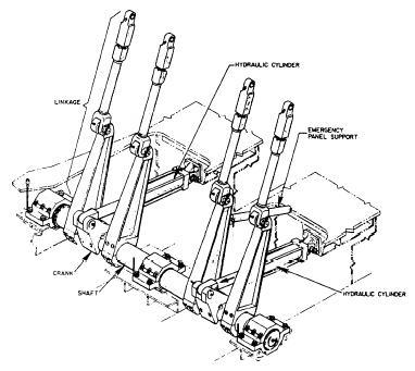
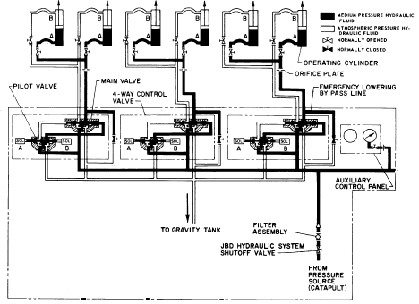
aft doors cylinders and the shuttle valve on the nose gear cylinder to close off the normal port and operate these cylinders. The nose gear cylinder extends; this unlocks the uplock and extends the nose gear. The nitrogen flowing into the aft door cylinders opens the aft doors. Fluid on the close side of the door cylinder is vented to return through the actuated dump valves. Nitrogen from another bottle actuates the shuttle valves on the uplock cylinders. Nitrogen flows into the uplock cylinders and causes them to disengage the uplocks. As soon as the uplocks are disengaged, the main gear extends by the force of gravity. Fluid on the up side of the main gear cylinders is vented to return through the actuated dump valves, preventing a fluid lock.Jet blast deflectors (JBD) onboard aircraft carriers are raised and lowered by hydraulic cylinders through mechanical linkage. Two hydraulic cylinders are attached to each JBD panel shaft by crank assemblies. (See fig. 12-9.) The shaft is rotated by the push and pull operation of the hydraulic cylinders. Shaft rotation extends or retracts the linkage to raise or lower the JBD panels. This operation is designed so that in the event of a failure of one of the hydraulic cylinders, the other one will raise or lower the panels. Figure 12-10 is a diagram of the hydraulic control system of a JBD during the raise cycle. Hydraulic fluid from the catapult hydraulic supply system is supplied to the JBD hydraulic system through an isolation valve and a filter to the 4-way control valve assembly. (The 4-way control valve assembly consists of a pilot-operated control valve, a direct- or solenoid-operated control valve, and a sequence valve, which is not shown.) To raise the JBD, solenoid B of the 4-way control valve assembly is energized. The spools of the 4-way valve assembly shift, allowing medium-pressure hydraulic fluid to flow into port A of the hydraulic cylinder. The cylinders extend,
Figure 12-9.Operating gear assembly (panels raised).
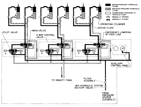
pushing the crank assembly aft and rotating the shaft. The rotation of the shaft extends the operating gear linkage and raises the panel assemblies. Fluid from port B of the piston is directed through the 4-way valve assembly and back to the gravity tank.To lower the JBD (fig. 12-11), solenoid A of the 4-way control valve assembly is energized. The spools of the 4-way valve assembly shift, allow medium-pressure hydraulic fluid to flow into port B of the hydraulic cylinder. The cylinders retract, pulling the crank assembly forward and rotating the shaft. The rotation of the shaft retracts the operating gear linkage and lowers the panel assemblies. Fluid from port A of the piston is directed through the 4-way valve assembly and back to the gravity tank.To lower the JBD in the event of hydraulic control failure, each JBD panel is equipped with a manual bypass valve, which allows bypassing the 4-way control valve. This allows venting the hydraulic pressure from the "raise" side of the cylinder back to the gravity tank.The three lines to port A of the hydraulic cylinders have orifice assemblies in them. These orifice assemblies control the flow of hydraulic fluid in both the raise and lower operations. |
 
|
|
|
||