Custom Search
|
|
 
|
||
|
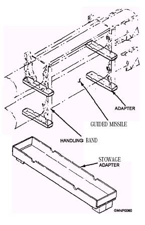
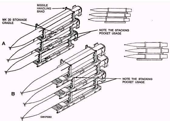
GUIDED MISSILE STOWAGE ADAPTER.- The Mk 100 guided missile stowage adapter is shown in figure 2-45. It is a simple aluminum alloy weldment that fits along the top and bottom of a handling band. The adapter adds support to the bands when missiles are stacked as shown in the figure. The Mk 100 stowage adapter is normally used when Mk 20 stowage cradles are not available. STOWAGE CRADLE.- The Mk 20 stowage cradle is shown in figure 2-46. It is a welded aluminum frame with four lifting eyes and two forklift pockets. Three cradle guides accept and lock the Mk 79 handling bands in place. Stacking pockets are provided on the bottom of the side rails (frame) of the cradle. Figure 2-47 illustrates various missile stacking arrangements using a Mk 20 cradle. (Three rounds high is the limit.) The cradle can also be used to load/unload a Mk 6 transfer dolly if a forklift truck is available. GUIDED MISSILE BAND STOWAGE
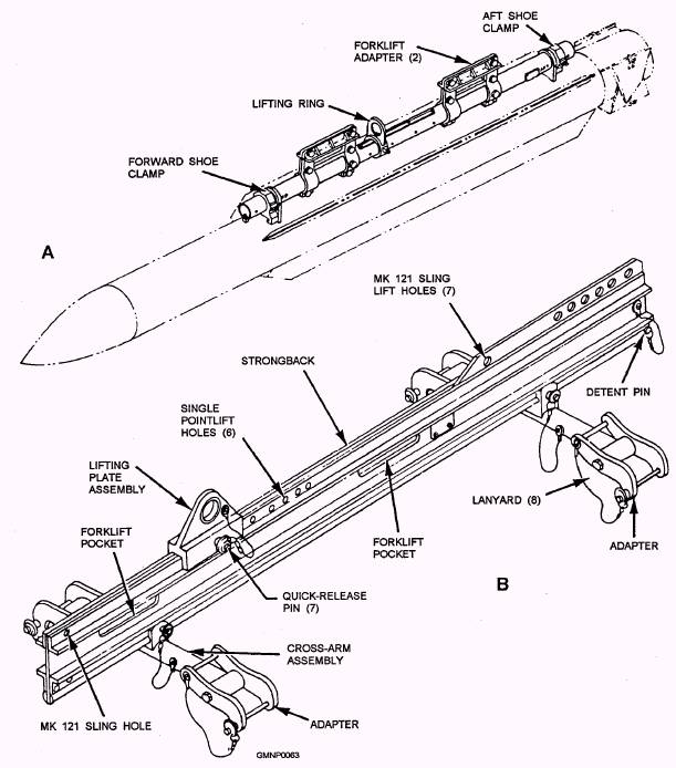
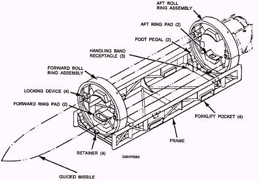
Figure 2-45.-Mk 100 guided missile stowage adapter. HOISTING BEAMS.- Figure 2-48 shows two common hoisting beams. These devices are often called handling beams or strongbacks. Generally, a hoisting beam attaches to the shoes of the round or to its handling bands. The round can then be lifted out of its shipping container by a forklift, truck, or crane. The missile is then transferred to a Mk 20 stowage cradle or a dolly loading stand. Of course, this sequence can be reversed to reload a container. The Mk 5 hoisting beam (view A) handles Standard missiles. It is manually connected to the shoes of the missile. The two shoe clamps slide over the upper shoes of the round. The Mk 15 hoisting beam (view B) can be adjusted to handle all rounds. Instead of clamping to the missile shoes, it attaches to the Mk 79 handling bands. The adapters and cross-arm assemblies can be adjusted to different load lengths. The lifting plate assembly can also be moved to obtain the correct center of gravity for different loads. DOLLY LOADING STAND.- The Mk 8 dolly loading stand is shown in figure 2-49. It is adaptable for Standard missiles. The stand is used to load/unload a Mk 6 transfer dolly. You might also hear the Mk 8 loading stand called a roll stand or (simply) a load stand. The stand is a braced, tubular aluminum frame. Two roll ring assemblies are mounted near the ends of the frame. Each ring assembly consists of two separate and removable sections or halves. A ring-locking mechanism is part of each roll ring assembly. Normally, the locking mechanism is engaged and prevents the ring assembly from rotating. Depressing a foot pedal (not shown in the figure) disengages the lock mechanism. The roll ring assembly is then free to be turned. The frame also mounts three pairs of handling band saddles and has a pair of forklift truck pockets. When handling Standard missiles, the top roll ring halves must be removed. The forward and aft missile shoes are guided into and supported by shoe pockets in the lower ring halves. Handling bands are not required in this type of handIing operation. The stand also provides a means to rotate Standard missiles. Once a missile is loaded into the lower ring halves, the top ring halves are reinstalled and clamped. Depressing the foot pedals unlocks the roll ring assemblies and the missile can be rotated/rolled. A missile may be rolled to ease minor maintenance actions also.
Figure 2-46.-Mk 20 stowage cradle.
Figure 2-47.-Stacking configurations available with the Mk 20 stowage cradle: A. Staggered-aft method; B. Alternate staggering method.
Figure 2-48.-View A. A Mk 5 hoisting beam attached to a missile; View B. A Mk 15 hoisting beam.
Figure 2-49.-Mk 8 dolly loading stand. |
 
|
|
|
||