Custom Search
|
|
 
|
||
|
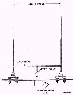
WHIP ANTENNAS Whip antennas are used for medium- and high-frequency transmitting and receiving systems. For low-frequency systems, whip antennas are used only for receiving. Essentially self-supporting, whip antennas may be deck-mounted or mounted on brackets on the stacks or superstructure. The self-supporting feature of the whip makes it particularly useful where space is limited and in locations not suitable for other types of antennas. Whip antennas can be tilted, a design feature that makes them suited for use along the edges of aircraft carrier flight decks. Aboard submarines, they can be retracted into the sail structure. Whip antennas commonly used aboard ship are 25, 28, or 35 feet long and consist of several sections. The 35-foot whip is most commonly used. If these antennas are mounted less than 25 feet apart, they are usually connected with a crossbar with the feed point at its center. The twin whip antenna (figure 2-25) is not broadband and is generally equipped with a base tuning unit. VHF AND UHF ANTENNAS The physical size of VHF and UHF antennas is relatively small because of the short wavelengths at these frequencies. Aboard ship, these antennas are installed as high and as much in the clear as possible.
Figure 2-25.-Twin whip antenna with crowbar. Since VHF and UHF antennas are line-of-sight systems, they require a clear area at an optimum height on the ship structure or mast. Unfortunately, this area is also needed for various radars and UHF direction-finding and navigational aid systems. VHF and UHF antennas are usually installed on stub masts above the foremast and below the UHF direction finder. UHF antennas are often located on the outboard ends of the yardarms and on other structures that offer a clear area. For best results in the VHF and UHF ranges, both transmitting and receiving antennas must have the same polarization. Vertically polarized antennas are used for all ship-to-ship, ship-to-shore, and ground-to-air VHF/UHF communications. Usually, either a vertical half-wave dipole or a vertical quarter-wave antenna with ground plane is used. An example of a UHF half-wave (dipole) antenna is the AT-150/SRC, shown in
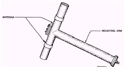
Figure 2-26.-AT-150/SRC UHF antenna.
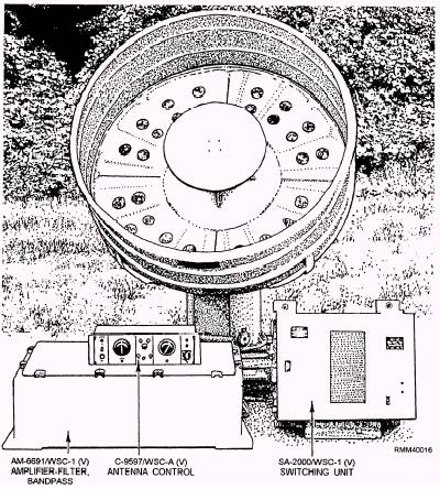
Figure 2-27.-OE-82C/WSC-1(V) antenna group.
Figure 2-26. This antenna is normally mounted horizontally.
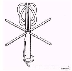
Figure 2-28.-AS-2815/SSR-1 antenna physical configuration. BROADBAND ANTENNAS Broadband antennas for HF and UHF bands have been developed for use with antenna multicouplers. Therefore, several circuits may be operated with a single atenna. Broadband antennas must be able to transmit or receive over a wide frequency band. HF broadband antennas include the 35-foot twin and trussed whips, half-cone, cage, and a variety of fan- designed antennas. The AT-150/SRC UHF antenna in figure 2-26 is an example of a broadband antenna. |
||
|
||