Custom Search
|
|
 
|
||
|
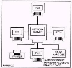
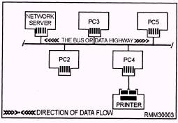
LAN CONFIGURATIONS (TOPOLOGIES) The physical arrangement of a LAN's components is called its configuration or topology. The three major types of LAN configurations, or topologies, are the star, the bus, and the ring. You can also create hybrid topologies by combining features of these configurations. For example, several bus networks can be joined together to form a ring of buses. Each topology requires LAN components to be connected in a different arrangement. These components are also referred to as nodes. Remember, a node is any point on a network where data can be sent (transmitted) or received\a workstation, server, and so on. The Star Network In a star network, each component is connected directly to the central computer or network server, as shown in figure 1-2. Only one cable is required from the central computer to each PC's network interface card to tie that workstation to the LAN. The star is one of the earliest types of network topologies. It uses the same approach to sending and receiving messages as our phone system. Just as a telephone call from one person to another is handled by a central switching station, all messages must go through the central computer or network server that controls the flow of data. You can easily add new workstations to the network without interrupting other nodes. This is one of the advantages of the star topology. Another advantage of star topology is that the network administrator can give selected nodes a higher priority status than others. The central computer looks for signals from these higher priority workstations before recognizing other nodes. Also, the star topology permits centralized diagnostics (troubleshooting) of all functions. It can do this because all messages must first go through the central computer. This can prove invaluable for ensuring network security has not been breached. So much for the good news; now for the bad news, or the disadvantages of the star network. Of all the topologies, the star is the least reliable because it has a single point of failure. The network relies mainly on the central computer for all functions. If it fails, all nodes also stop functioning, resulting in failure of the entire network. This is precisely the same weakness multi-user computer systems have that rely on a central processor. The Bus Network The bus topology is like a data highway. That is, all components or nodes are connected to the same cable,
Figure 1-2.\A star network topology. and the far ends of this cable never meet (see figure 1-3). Bus LANs are best suited to applications involving relatively low usage of the bus coupled with the need to pass relatively short messages from one node to another. In many such networks, the workstations check whether a message is coming down the highway before sending their messages. Since all nodes share the bus, all messages must pass through the other workstations on the way to their destinations. Each node checks the address attached to the message to see if it matches its own address. Bus topologies allow individual nodes to be out of service or to be moved to new locations without disrupting service to the remaining nodes. Unlike the star topology, where dozens of cables come together at the central computer causing logistical problems, bus cabling is simple. The bus topology is very reliable, because if any node on the bus network fails, the bus itself is NOT affected, and the remaining nodes can continue to operate without interruption. Many of the low-cost LANs use a bus topology and twisted-pair wire cabling. A disadvantage of the bus topology is that generally there must be a minimum distance between workstations to avoid signal interference. Another disadvantage is that nodes must contend with each other for the use of the bus. Simultaneous transmissions by more than one node are NOT permitted. This problem, however, can be solved by using one of several types of systems designed to control access to the bus. They are collision detection, collision avoidance, and token passing, which we will discuss shortly. Also, there is no easy way for the network administrator to run diagnostics on the entire network. Finally, the bus network can be easily compromised by an unauthorized network user, since all messages are sent along a common data highway. For this reason, it is difficult to maintain network security.
Figure 1-3.\A bus network topology.
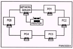
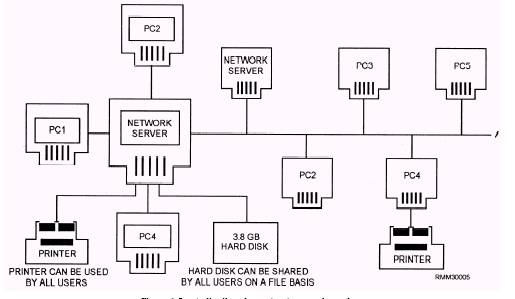
Figure 1-4.\A ring network topology. The Ring Network In a ring network, all of the components or nodes are connected to the main cable, and the cable forms a ring, as shown in figure 1-4. This topology allows a node to send a message to another node on the ring. However, the message must be transmitted through each node until it reaches its destination. Messages proceed from node to node in one direction only. Should anode fail on the network, data can no longer be passed around the ring unless the failed node is either physically or electronically bypassed. Using bypass software, the network can withstand the failure of a workstation by bypassing it and still be able to maintain the network's integrity. One of the major issues in a ring topology is the need for ensuring all workstations have equal access to the network. One of the major disadvantages of ring topologies is the extreme difficulty of adding new workstations while the network is in operation. Normally, the entire network has to be brought down while a new node is added and cabling reattached. However, this particular problem can be overcome by initially setting up the network with additional connectors. These connectors enable you to add or remove nodes while the network remains intact and in operation. The addition of the connectors is accomplished with the addition of a multistation access unit (MAU). The MAU is a wiring concentrator which allows workstations to be either inserted or bypassed on the ring. The Distributed Star (Tree) Network The distributed star or tree topology (figure 1 -5) can provide many of the advantages of the bus and the star topologies. It connects workstations to a central point, called a hub. This hub can support several workstations or hubs which, in turn, can support other workstations. Distributed star topologies can be easily adapted to the physical arrangement of the facility site. If the site has a high concentration of workstations in a given area, the system can be configured to more closely resemble a
Figure 1-5.\A distributed star (tree) network topology. star topology. If the workstations are widely dispersed, the system can use inexpensive hubs with long runs of shared cable between hubs, similar to the bus topology. |
||
|
||