| Tweet |

Custom Search
|
|
 
|
||
|
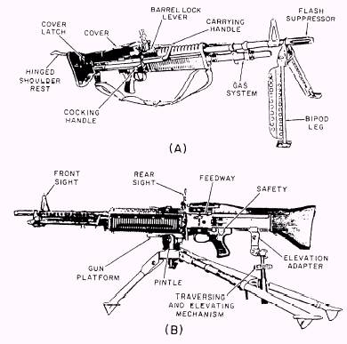
MOSSBERG M500 SHOTGUN While very similar to the M870, the Mossberg M500 has a few significant differences. The following is a brief description of differences that affect operation of the weapon. Figure 8-28 illustrates the location of the safety button and the action locklever on the M500 shotgun. The M500 safety button is located on the top of the receiver, and the action locklever is to the rear of the trigger guard. But the M870 has the safety button in the trigger guard, and the action bar lock to the front of the trigger guard. The disassembly and maintenance of the M500 is basically the same as that of the M870 so much so that they are both currently covered on the same MRC. Further information on the Mossberg M500 shotgun may be found in the manufacturer's owner's manual supplied with the weapon. 7.62-MM M60 MACHINE GUN LEARNING OBJECTIVES: List the essential features and describe the operation of the M60 machine gun. The M60 machine gun (fig. 8-29) is an air-cooled, belt-fed, gas-operated automatic weapon. The machine gun was originally developed for use by
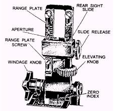
Figure 8-29.-M60 machine gun: (A) Bipod mounted; (B) Tripod mounted. ground troops; however, it is used on many types and classes of ships, river patrol craft, and combat helicopters. Essential features of the M60 are as follows: Length . . . . . . . . . . . . . . . . 43.5 in. (110.5 cm) Weight . . . . . . . . . . . . . . . . 23 lb (10.4 kg) Maximum range . . . . . . . . 3,725 meters (4,075 yd) Maximum effective range . . . . . . . . . . . . . . . . . 1,100 meters (1,200 yd) Ammunition . . . . . . . . . . . 7.62-mm ball tracer, armor-piercing, incendiary, and dummy Rates of fire: Sustained . . . . . . . . . . . . . . 100 rounds per minute Rapid . . . . . . . . . . . . . . . . . 200 rounds per minute Cyclic . . . . . . . . . . . . . . . . 550 rounds per minute The M60 has a front sight permanently affixed to the barrel. The rear sight leaf is mounted on a springtype dovetail base (fig. 8-30). It can be folded forward to the horizontal when the gun is to be moved. The range plate on the sight leaf is marked for each 100 meters, from 300 meters to the maximum effective range of 1100 meters. Range changes may be made by using either the slide release or the elevating knob. The slide release is used for making major changes in elevation. The elevating knob is used for fine adjustments, such as during zeroing. Four clicks on the elevating knob equal a 1-mil change of elevation. The sight is adjustable for windage 5 roils right and left of zero. The windage knob is located on the left side of the sight. One click on the windage knob equals a 1-mil change of deflection. NOTE One mil equals 1 inch at 1000 inches, 1 yard at 1000 yards, 1 meter at 1000 meters, etc. A safety lever is located on the left side of the trigger housing. It has an S (SAFE) and an F (FIRE) position. On the SAFE position the bolt cannot be pulled to the rear or released to go forward. The cocking lever, on the right side of the gun, is used to pull the bolt to the rear. It must be returned manually to its forward position each time the bolt is manually pulled to the rear.
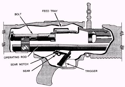
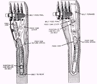
Figure 8-30.-M60 rear sight. OPERATION The machine gun is designed to function automatically as long as ammunition is fed into the gun and the trigger is held to the rear. Each time a round is fired, the parts of the machine gun function in a certain sequence. Many of the actions occur simultaneously and are only separated for teaching purposes. The sequence of operation is known as the cycle of operation. The cycle starts by putting a round in the feed tray groove and then pulling the trigger, releasing the sear from the sear notch (fig. 8-31). It stops when the trigger is released and the sear again engages the sear notch in the operating rod. When the trigger is held to the rear, the rear of the sear is lowered and disengaged from the sear notch. This allows the operating rod and bolt to be driven forward by the expansion of the operating rod spring. Now that the gun is functioning, the steps of the cycle can be traced. As the bolt begins its forward movement, the feed cam is forced to the right, causing the feed cam lever to pivot in the opposite direction and forcing the feed pawl over the next round in the belt, ready to place it in the feed tray groove when the rearward action occurs again. As the bolt moves to the rear (fig. 8-32) after the firing, the cam roller on the top of the bolt forces the feed cam to the left. The feed cam lever is forced to pivot, moving the feed pawl to the right, placing a round in the feed tray groove. As the bolt travels forward, the upper locking lug engages the rim of the cartridge. The pressure of the front and rear cartridge guides hold the round so that
Figure 8-31.-Sear disengaging from sear notch.
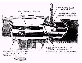
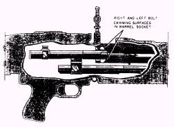
Figure 8-32.-Feeding. positive contact is made with the upper locking lug of the bolt. The front cartridge guide prevents the link's forward motion as the round is stripped from the belt, The upper locking lug carries the round forward, and the cambering ramp causes the nose of the cartridge to be caromed downward into the chamber as shown in figure 8-33. When the round is fully seated in the chamber, the extractor snaps over the rim of the cartridge, and the ejector on the face of the bolt is depressed. As the round is chambered, the bolt enters the barrel socket. The upper and lower locking lugs contact the bolt caroming surfaces inside the barrel socket and start the rotation of the bolt clockwise. The action of the operating rod yoke against the bolt caroming slot, as the operating rod continues forward, causes the bolt to complete its one-quarter turn clock- wise rotation (fig. 8-34). Locking is then completed. After the bolt reaches its fully forward and locked position, the operating rod continues to go forward,
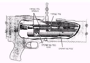
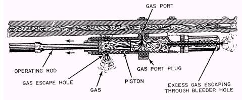
Figure 8-33.-Chambering. independently of the bolt, for a short distance. The yoke, engaged between the firing pin spools, carries the firing pin forward. The striker of the firing pin protrudes through the aperture in the face of the bolt, strikes the primer of the cartridge and detonates it. This action is depicted in figure 8-35. After the cartridge is ignited and the projectile passes the gas port, part of the expanding gases enter the gas cylinder through the gas port. The rapidly expanding gases enter the hollow gas piston as shown in figure 8-36, and force the piston to the rear. The operating rod, being in contact with the piston, is also pushed to the rear. As the operating rod continues to the rear, the operating rod yoke acts against the bolt camming slot to cause the bolt to begin its counter- clockwise rotation. The upper and lower locking lugs of the bolt, contacting the bolt caroming surfaces in- side the barrel socket, cause the bolt to complete its one-quarter turn rotation (counterclockwise) and un- lock the bolt from the barrel socket. Unlocking begins as the yoke of the operating rod contacts the curve of the bolt caroming slot, and ends as the bolt clears the end of the barrel socket. While unlocking is going on, extraction is beginning. The rotation of the bolt (in unlocking) loosens the cartridge case in the chamber. As the operating rod and bolt continue to the rear, the extractor (gripping the rim of the cartridge) pulls the cartridge case from the chamber. As the case is withdrawn from the chamber, the ejector spring expands. The ejector presses on the base of the cartridge case, forcing the front of the spent case against the right side of the receiver, as shown in figure 8-37. As the bolt continues to the rear, the action of the ejector pushing against the base of the cartridge case and the extractor gripping the right side of the case cause
Figure 8-34.-Weapon locked, ready to fire.
Figure 8-35.-Firing.
Figure 8-36.-Unlocking action of gases. the cartridge case to spin from the gun as the case reaches the ejection port. The empty link is forced out of the link ejection port as the rearward movement of the bolt causes the next round to be positioned in the feed plate groove. As the expanding gases force the gas piston to the rear, the operating rod is initially moved independently of the bolt. The yoke of the operating rod acts against the rear firing pin spool, withdrawing the firing pin from the primer of the spent cartridge case. The action of the operating rod yoke continuing to the rear against the rear firing pin spool fully compresses the firing pin spring. As long as the trigger is held to the rear, the weapon will continue to complete the first seven steps of functioning automatically. When the trigger is released and the sear again engages the sear notch, the cycle of functioning is stopped and the weapon is cocked.
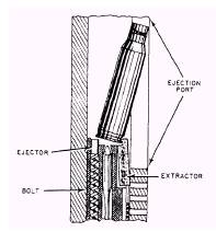
Figure 8-37.-Extraction and ejection. For further information on the M60 machine gun refer to U.S. Army TM 9-1005-224-24 and TM 9-1005-24-10. |
||
|
||