|
VOLTAGE DIVIDER WITH POSITIVE AND NEGATIVE VOLTAGE REQUIREMENTS
In many cases the load for a voltage divider requires both positive and negative voltages. Positive and negative voltages can be supplied from a single source voltage by connecting the ground (reference point) between two of the divider resistors. The exact point in the circuit at which the reference point is placed depends upon the voltages required by the loads.
For example, a voltage divider can be designed to provide the voltage and current to three loads from a given source voltage.
Given:

The circuit is drawn as shown in figure 3-66. Notice the placement of the ground reference point. The values for resistors R1, R3, and R4 are computed exactly as was done in the last example. IR1 is the bleeder current and can be calculated as follows:
Figure 3-66. - Voltage divider providing both positive and negative voltages.

Solution:

Calculate the value of R1.
Solution:

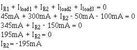
Calculate the current through R2 using Kirchhoff's current law.
At point A:

(or 195mA leaving point A)
Since ER2 = E load 2, you can calculate the value of R2.
Solution:

Calculate the current through R3.

The voltage across R3 (ER3) equals the difference between the voltage requirements of loads 3 and 2.
Solution:

Calculate the value of R3.
Solution:

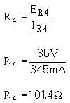
Calculate the current through R4.

The voltage across ER4 equals the source voltage (Es) minus the voltage requirement of load 3 and the voltage requirement of load 1. Remember Kirchhoff's voltage law which states that the sum of the voltage drops and emfs around any closed loop is equal to zero.
Solution:

Calculate the value of R4.
Solution:

With the calculations just explained, the values of the resistors used in the voltage /divider are as follows:

From the information just calculated, any other circuit quantity, such as power, total current, or resistance of the load, could be calculated.
|
|


