Custom Search
|
|
  |
|
|
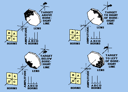
ELECTRONIC SCANNING. - Electronic scanning can accomplish lobe motion more rapidly than, and without the inherent maintenance disadvantages of, the mechanical systems. Because electronic scanning cannot generally cover as large an area of space, it is sometimes combined with mechanical scanning in particular applications. With MONOPULSE (SIMULTANEOUS) LOBING, all range, bearing, and elevation-angle information of a target is obtained from a single pulse. Monopulse scanning is used in fire-control tracking radars. For target tracking, the radar discussed here produces a narrow circular beam of pulsed-rf energy at a high pulse-repetition rate. Each pulse is divided into four signals which are equal both in amplitude and phase. These four signals are radiated at the same time from each of four feedhorns that are grouped in a cluster. The resulting radiated energy is focused into a beam by a microwave lens. Energy reflected from targets is refocused by the lens back into the feedhorns. The total amount of the energy received by each horn varies, depending on the position of the target relative to the beam axis. This is illustrated in figure 1-19 for four targets at different positions with respect to the beam axis. Note that a phase inversion takes place at the microwave lens similar to the image inversion that takes place in an optical system. Figure 1-19. - Monopulse scanning.
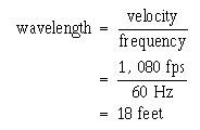
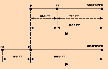
The amplitude of returned signals received by each horn is continuously compared with those received in the other horns. Error signals are generated which indicate the relative position of the target with respect to the axis of the beam. Angle servo circuits receive these error signals and correct the position of the radar beam to keep the beam axis on target. The TRAVERSE (BEARING) SIGNAL is made up of signals from horn A added to C and from horn B added to D. By waveguide design, the sum of B and D is made 180 degrees out of phase with the sum of A and C. These two are combined and the traverse signal is the difference of (A + C) - (B + D). Since the horns are positioned as shown in figure 1-19, the relative amplitudes of the horn signals give an indication of the magnitude of the traverse error. The elevation signal consists of the signals from horns C and D added 180 degrees out of phase with horns A and B [(A + B) - (C + D)]. The sum, or range, signal is composed of signals from all four feedhorns added together in phase. It provides a reference from which target direction from the center of the beam axis is measured. The range signal is also used as a phase reference for the traverse and elevation-error signals. The traverse and elevation error signals are compared in the radar receiver with the range or reference signal. The output of the receiver may be either positive or negative pulses; the amplitudes of the pulses are proportional to the angle between the beam axis and a line drawn to the target. The polarities of the output pulses indicate whether the target is above or below, to the right or to the left of the beam axis. Of course, if the target is directly on the line of sight, the output of the receiver is zero and no angle-tracking error is produced. An important advantage of a monopulse-tracking radar over radar using conical scan is that the instantaneous angular measurements are not subject to errors caused by target SCINTILLATION. Scintillation can occur as the target maneuvers or moves and the radar pulses bounce off different areas of the target. This causes random reflectivity and may lead to tracking errors. Monopulse tracking radar is not subject to this type of error because each pulse provides an angular measurement without regard to the rest of the pulse train; no such cross-section fluctuations can affect the measurement. An additional advantage of monopulse tracking is that no mechanical action is required. ELECTRONIC SCANNING used in search radar systems was explained in general terms earlier in this chapter during the discussion of elevation coverage. This type of electronic scanning is often called FREQUENCY SCANNING. An in-depth explanation of frequency scanning theory can be found in the fire control technician rate training manuals. Radar systems are normally divided into operational categories based on energy transmission methods. Up to this point, we have mentioned only the pulse method of transmission to illustrate basic radar concepts. Although the pulse method is the most common method of transmitting radar energy, two other methods are sometimes used in special applications. These are the continuous-wave (cw) method and the frequency modulation (fm) method. All three basic transmission methods are often further subdivided to designate specific variations or combinations. CONTINUOUS-WAVE METHOD When radio-frequency energy transmitted from a fixed point continuously strikes an object that is either moving toward or away from the source of the energy, the frequency of the reflected energy is changed. This shift in frequency is known as the DOPPLER EFFECT. The difference in frequency between the transmitted and reflected energy indicates both the presence and the speed of a moving target. Doppler Effect A common example of the Doppler effect in action is the changing pitch of the whistle of an approaching train. The whistle appears to change pitch from a high tone, as the train approaches, to a lower tone as it moves away from the observer. As the train approaches, an apparent increase in frequency (an increase in pitch) is heard; as the train moves away, an apparent decrease in frequency (a decrease in pitch) is heard. This pitch variation is known as the Doppler effect. Let's examine the reason for this apparent change in pitch. Assume that the transmitter emits an audio signal at a frequency of 60 hertz and that the transmitter is traveling at a velocity of 360 feet per second (fps). At the end of 1 second, the transmitter will have moved from point P to point P1 as shown in view A of figure 1-20. The total distance from point P to the observer is 1,080 feet. The velocity of sound is 1,080 feet per second; thus, a sound emitted at point P will reach the observer in 1 second. To find the wavelength of this transmitted signal, you divide the velocity of the signal (1,080 fps) by the frequency (60 hertz). The result is 18 feet, as shown below:
Figure 1-20. - Transmitter moving relative to an observer.
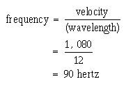
In 1 second the transmitter moves 360 feet and transmits 60 hertz. At the end of 1 second, the first cycle of the transmitted signal reaches the observer, just as the sixtieth cycle is leaving the transmitter at point P1. Under these conditions the 60 hertz emitted is located between the observer and point P1. Notice that this distance is only 720 feet (1,080 minus 360). The 60 hertz is spread over the distance from point P1 to the observer and has a wavelength of just 12 feet (720 divided by 60). To find the new frequency, use the following formula:
The original frequency, 60 hertz, has changed to an apparent frequency of 90 hertz. This new frequency only applies to the observer. Notice that the Doppler frequency variation is directly proportional to the velocity of the approaching transmitter. The faster the transmitter moves toward the observer, the greater the number of waves that will be crowded into the space between the transmitter and the observer. Suppose the transmitter were stationary and the observer moving. When approaching the transmitter, the observer would encounter waves per unit of time. As a result, the observer would hear a higher pitch than the transmitter would actually emit. If the transmitter were traveling away from the observer, as shown in view B of figure 1-20, the first cycle would leave the transmitter at point P and the sixtieth at point P2. The first cycle would reach the observer when the transmitter reached P2. You would then have 60 cycles stretched out over 1,080 plus 360 feet, a total of 1,440 feet. The wavelength of these 60 hertz is 1,440/60, or 24 feet. The apparent frequency is 1,080 divided by 24, or 45 hertz. Uses of CW Doppler System The continuous-wave, or Doppler, system is used in several ways. In one radar application, the radar set differentiates between the transmitted and reflected wave to determine the speed of the moving object. The Doppler method is the best means of detecting fast-moving objects that do not require range resolution. As a moving object approaches the transmitter, it encounters and reflects more waves per unit of time. The amount of frequency shift produced is very small in relation to the carrier frequency. This is because the velocity of propagation of the signal is very high compared to the speed of the target. However, because the carrier frequencies used in radar are high, larger frequency shifts (in the audio-frequency range) are produced. The amount of shift is proportional to the speed of the reflecting object. One-quarter cycle shift at 10,000 megahertz will provide speed measurements accurate to a fraction of a percent. If an object is moving, its velocity, relative to the radar, can be detected by comparing the transmitter frequency with the echo frequency (which differs because of the Doppler shift). The DIFFERENCE or BEAT FREQUENCY, sometimes called the DOPPLER FREQUENCY (fd), is related to object velocity. The separation of the background and the radar contact is based on the Doppler frequency that is caused by the reflection of the signal from a moving object. Disadvantages of the Doppler system are that it does not determine the range of the object, nor is it able to differentiate between objects when they lie in the same direction and are traveling at the same speed. Moreover, it does not "see" stationary or slow-moving objects, which a pulse radar system can detect. To track an object with cw Doppler, you must determine the radar range. Since the Doppler frequency is not directly related to range, another method is needed to determine object range. By using two separate transmitters that operate at two different frequencies (f1 and f2), you can determine range by measuring the relative phase difference between the two Doppler frequencies. In such a system, a mixer is used to combine the two transmitted frequencies and to separate the two received frequencies. This permits the use of one transmitting and receiving antenna. Instead of using two transmitter frequencies, you can find the range by sweeping the transmitter frequency uniformly in time to cover the frequency range from f1 to f2. The beat, or difference, frequency between the transmitted and received signals is then a function of range. In this type of radar, the velocity as well as range is measured. Q.24 The Doppler effect causes a change in what aspect of rf energy that strikes a
moving object? |
 
|
|
|
Integrated Publishing, Inc. - A (SDVOSB) Service Disabled Veteran Owned Small Business
|