Custom Search
|
|
  |
|
|
THREE-PHASE ROTATING FIELDS
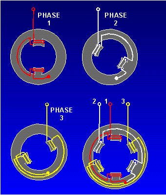
The three-phase induction motor also operates on the principle of a rotating magnetic field. The following discussion shows how the stator windings can be connected to a three-phase ac input and have a resultant magnetic field that rotates. Figure 4-4, views A-C show the individual windings for each phase. Figure 4-4, view D, shows how the three phases are tied together in a Y-connected stator. The dot in each diagram indicates the common point of the Y-connection. You can see that the individual phase windings are equally spaced around the stator. This places the windings 120 apart. Figure 4-4. - Three-phase, Y-connected stator.
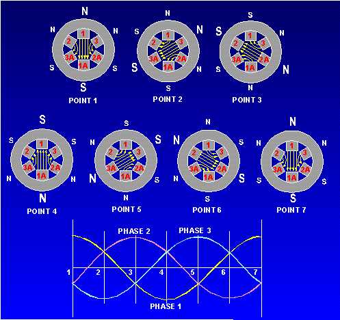
The three-phase input voltage to the stator of figure 4-4 is shown in the graph of figure 4-5. Use the left-hand rule for determining the electromagnetic polarity of the poles at any given instant. In applying the rule to the coils in figure 4-4, consider that current flows toward the terminal numbers for positive voltages, and away from the terminal numbers for negative voltages. Figure 4-5. - Three-phase rotating-field polarities and input voltages.
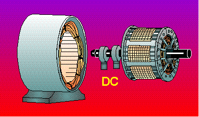
The results of this analysis are shown for voltage points 1 through 7 in figure 4-5. At point 1, the magnetic field in coils 1-1A is maximum with polarities as shown. At the same time, negative voltages are being felt in the 2-2A and 3-3A windings. These create weaker magnetic fields, which tend to aid the 1-1A field. At point 2, maximum negative voltage is being felt in the 3-3A windings. This creates a strong magnetic field which, in turn, is aided by the weaker fields in 1-1A and 2-2A. As each point on the voltage graph is analyzed, it can be seen that the resultant magnetic field is rotating in a clockwise direction. When the three-phase voltage completes one full cycle (point 7), the magnetic field has rotated through 360. Q.6 What is the major difference between a two-phase and a three-phase stator? ROTOR BEHAVIOR IN A ROTATING FIELD For purposes of explaining rotor movement, let's assume that we can place a bar magnet in the center of the stator diagrams of figure 4-5. We'll mount this magnet so that it is free to rotate in this area. Let's also assume that the bar magnet is aligned so that at point 1 its south pole is opposite the large N of the stator field. You can see that this alignment is natural. Unlike poles attract, and the two fields are aligned so that they are attracting. Now, go from point 1 through point 7. As before, the stator field rotates clockwise. The bar magnet, free to move, will follow the stator field, because the attraction between the two fields continues to exist. A shaft running through the pivot point of the bar magnet would rotate at the same speed as the rotating field. This speed is known as synchronous speed. The shaft represents the shaft of an operating motor to which the load is attached. Remember, this explanation is an oversimplification. It is meant to show how a rotating field can cause mechanical rotation of a shaft. Such an arrangement would work, but it is not used. There are limitations to a permanent magnet rotor. Practical motors use other methods, as we shall see in the next paragraphs. SYNCHRONOUS MOTORS The construction of the synchronous motors is essentially the same as the construction of the salient-pole alternator. In fact, such an alternator may be run as an ac motor. It is similar to the drawing in figure 4-6. Synchronous motors have the characteristic of constant speed between no load and full load. They are capable of correcting the low power factor of an inductive load when they are operated under certain conditions. They are often used to drive dc generators. Synchronous motors are designed in sizes up to thousands of horsepower. They may be designed as either single-phase or multiphase machines. The discussion that follows is based on a three-phase design. Figure 4-6. - Revolving-field synchronous motor.
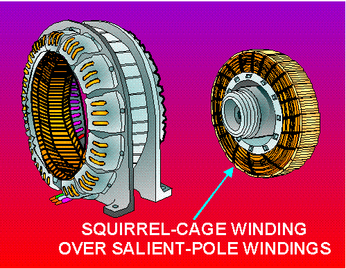
To understand how the synchronous motor works, assume that the application of three-phase ac power to the stator causes a rotating magnetic field to be set up around the rotor. The rotor is energized with dc (it acts like a bar magnet). The strong rotating magnetic field attracts the strong rotor field activated by the dc. This results in a strong turning force on the rotor shaft. The rotor is therefore able to turn a load as it rotates in step with the rotating magnetic field. It works this way once it's started. However, one of the disadvantages of a synchronous motor is that it cannot be started from a standstill by applying three-phase ac power to the stator. When ac is applied to the stator, a high-speed rotating magnetic field appears immediately. This rotating field rushes past the rotor poles so quickly that the rotor does not have a chance to get started. In effect, the rotor is repelled first in one direction and then the other. A synchronous motor in its purest form has no starting torque. It has torque only when it is running at synchronous speed. A squirrel-cage type of winding is added to the rotor of a synchronous motor to cause it to start. The squirrel cage is shown as the outer part of the rotor in figure 4-7. It is so named because it is shaped and looks something like a turnable squirrel cage. Simply, the windings are heavy copper bars shorted together by copper rings. A low voltage is induced in these shorted windings by the rotating three-phase stator field. Because of the short circuit, a relatively large current flows in the squirrel cage. This causes a magnetic field that interacts with the rotating field of the stator. Because of the interaction, the rotor begins to turn, following the stator field; the motor starts. We will run into squirrel cages again in other applications, where they will be covered in more detail. Figure 4-7. - Self-starting synchronous ac motor.
To start a practical synchronous motor, the stator is energized, but the dc supply to the rotor field is not energized. The squirrel-cage windings bring the rotor to near synchronous speed. At that point, the dc field is energized. This locks the rotor in step with the rotating stator field. Full torque is developed, and the load is driven. A mechanical switching device that operates on centrifugal force is often used to apply dc to the rotor as synchronous speed is reached. The practical synchronous motor has the disadvantage of requiring a dc exciter voltage for the rotor. This voltage may be obtained either externally or internally, depending on the design of the motor. Q.7 What requirement is the synchronous motor specifically designed to meet? |
 
|
|
|
Integrated Publishing, Inc. - A (SDVOSB) Service Disabled Veteran Owned Small Business
|