 |
||
|
|
||
| |||||||||||||||
|
|
LAYOUT OF STRUCTURAL SHAPES Structural shapes are slightly more difficult to lay out than plate. This is because the layout lines may not be in view of the layout person at all times. Also, the reference line may not always be in view. Steel beams are usually fabricated to fit up to another beam. Coping and slotting are required to accomplish this. Figure 3-32 shows two W 10 x 39 beams being fitted up. Beam A is intersecting beam B at the center. Coping is required so beam A will butt up to the web of beam B; the connecting angles can be welded to the web, and the flanges can be welded together. A cut 1 1/8 inches (2.8 cm) long at 45 degrees at the end of the flange cope will allow the web to fit up under the flange of beam B and also allow for the fillet. The size of the cope is determined by dividing the flange width of the receiving beam in half and then subtracting one half of the thickness of the web plus 1/16 inch. This determines how far back on beam A the cope should be cut. When two beams of different sizes are connected, the layout on the intersecting beam is determined by whether it is larger or smaller than the intersected beam. In the case shown in figure 3-33, the
Figure 3-33.-Typical framed construction, top flange flush.
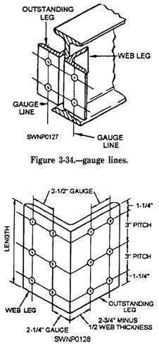
Figure 3-32.-Fabrication and fit-up for joining two beams of the same size. intersecting beam is smaller; therefore, only one flange is coped to fit the other. The top flanges will be flush. Note that the angles on this connection are to be bolted, rather than welded. CONNECTION ANGLE LAYOUT A very common connection with framed construction is the connection angle. The legs of the angles used as connections are specified according to the surface to which they are to be connected. The legs that attach to the intersecting steel to make the connections are termed web legs. The legs of the angles that attach to the supporting or intersected steel beam are termed outstanding legs. The lines in which holes in the angle legs are placed are termed gauge lines. The distances between gauge lines and known edges are termed gauges. An example of a completed connection is shown in figure 3-34. The various terms and the constant dimensions for a standard connection angle are shown in figure 3-35.
Figure 3-35.-Standard layout for connection angle using 4-inch by 4-inch angle The distance from the heel of the angle to the first gauge line on the web leg is termed the web leg gauge. This dimension has been standardized at 2 1/4 inches (5.6 cm). THIS DIMENSION IS CONSTANT AND DOES NOT VARY. The distance from the heel of the angle to the first gauge line on the outstanding leg is called the outstanding leg gauge. This dimension varies as the thickness of the member, or beam, varies. This variation is necessary to maintain a constant 5 1/2-inch-spread dimension on the angle connection. The outstanding leg gauge dimension can be determined in either one of the following two ways: 1. Subtract the web thickness from 5 1/2 inches (13.8 cm) and divide by 2. 2. Subtract 1/2 of the web thickness from 2 3/4 inches. The distance between holes on any gauge line is called pitch. This dimension has been standardized at 3 inches (7.5 cm). The end distance is equal to one half of the remainder left after subtracting the total of all pitch spaces from the length of the angle. By common practice, the angle length that is selected should give a 1 1/4-inch (3-cm) end distance. All layout and fabrication procedures are not covered in this section. Some examples are shown in figure 3-36. Notice that the layout and fabrication yard has a table designed to allow for layout, cutting, and welding with minimum movement of the structural members. The stock materials are stored like kinds of materials. The table holds two columns being fabricated out of beams with baseplates and cap plates. Angle clips for seated connections (fig. 3-37) should be installed before erection, |
|
Privacy Statement - Press Release - Copyright Information. - Contact Us - Support Integrated Publishing |