 |
||
|
|
||
| |||||||||||||||
|
|
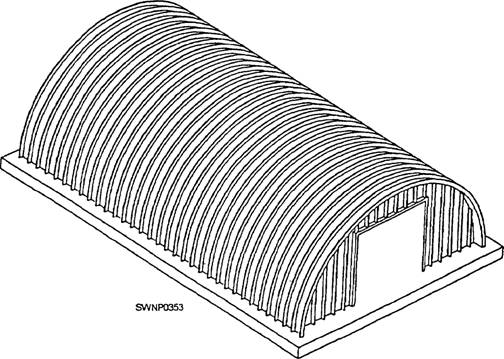
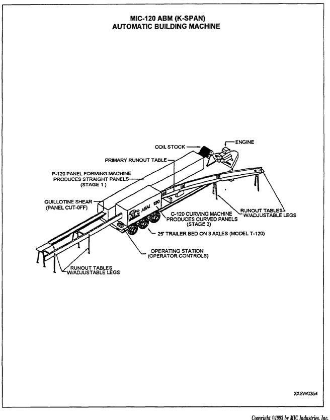
DISASSEMBLY PROCEDURES Disassembly of the pre-engineered building should not be difficult once you are familiar with the erection procedures. In disassembling a building, be sure and clearly mark or number all of the parts. Then you will know where the parts go when reassembling the building. The main steps of the disassembly procedures are as follows: 1. Remove the sheeting. 2. Remove the windows, the door leaves, and the end wall. 3. Remove the diagonal brace angles and the sag rods. 4. Remove the braces, the girts, and the purlins. 5. Let down the frames. K-SPAN BUILDINGS K-span buildings (fig. 8-10) are a new form of construction within the Seabee community. The intended uses of these buildings are as flexible as the pre-engineered buildings discussed earlier. ABM 120 SYSTEM The K-span building system consists of a self-contained, metal building manufacturing plant, known as the ABM 120 System/Automatic Building Machine 120. This machine is mounted on a trailer, forming a type of "mobile factory" (fig. 8-11) that is easily towed to even the remotest construction sites. An important aspect of this machine is that it can be transported by air anywhere in the world easily. In fact. the ABM System has been certified for air transport by the U.S. Air Force in C-130, C-141, and C-5 aircraft. Once the machine is delivered on site, it can be set up in minutes and turn coils of steel into structural
Figure 8-10.-Typical K-span building. strength arched panels. The panels are then machine seamed together to form an economical and watertight steel structure. The final shape and strength of the materials used cancels the need for columns, beams, or any other type of interior support. All of the panel-to-panel connections are joined using an electric automatic seaming machine. Because of this, there are no nuts, bolts, or any other type of fastener to slow down construction or create leaks. Once delivered to the jobsite, the "on-site" manufacturing abilities of the machine give the ABM operator complete control of fabrication as well as the quality of the building, Training key personnel in the operation of all related K-span equipment is essential. These crew members, once trained, can instruct other members of the crew in the safe fabrication and erection of a K-span. The following section gives you some, but not all, of the key elements associated with K-span construction. As with all equipment, always refer to the manufacturers' manuals. The main component of the K-span system is the trailer-mounted building machine (fig. 8-12). This figure shows the main components of the trailer and the general operating instructions. The primary position is the operator's station at the rear of the trailer (fig. 8-13). The crew member, selected for this position, must have a thorough understanding of the machine operations and the manuals. From that position, the operator controls all of the elements required to form the panels. First, the operator must run the coil stock through the machine to form the panel shape. Next, it is cut off at the correct length. This length is the required length for one arched panel to run continuously from one footer to the other. Last, after the panel is cut to length, it is run back through the machine to give it the correct arch. The operator must remain at the controls at all times. From the placement of the trailer on site to the completion of the curved panel, attention to detail is paramount as with all of the aspects of construction. As you operate the panel, you will be adjusting the various machine-operating components. Adjustments for the thickness, the radius, and the curving machine MUST be made according to the manuals. Do not permit shortcuts in adjustments. Any variations in adjustments or disregard for the instructions found in the operating manuals will leave you with a pile of useless material or an inconsistent building.
Figure 8-11.-Automatic Building Machine 120.
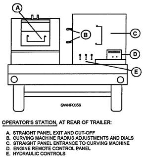
Figure 8-12.-Trailer-mounted machinery.
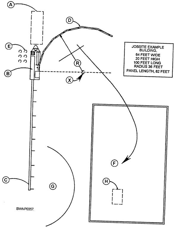
Figure 8-13.-Rear of K-span trailer. Machinery Placement Preplanning of the site layout is important to avoid setup problems. Uneven or sloped ground is not a concern as long as the bed of the trailer aligns with the general lay of the existing surface conditions. Using figure 8-14 as a guide when placing the machinery, you should consider factors such as the following: Maneuvering room for the towing of the trailer, or leave it attached to the vehicle (as shown at A). The length of the unit is 27 feet 8 inches long by 7 feet 4 inches wide (B). Allow enough room for run-out stands to hold straight panels. Stands have a net length of 9 feet 6 inches each(C). Find point X: From the center of the curve, measure the distance equal to the radius in line with the front of the curved frame. From point X, scribe an arc equal to the radius. This arc will define the path of the curved panel. Add 10 feet for run-out stands and legs (D). Storage area required to store the coil stock and access for equipment to load onto the machine (E).
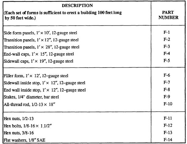
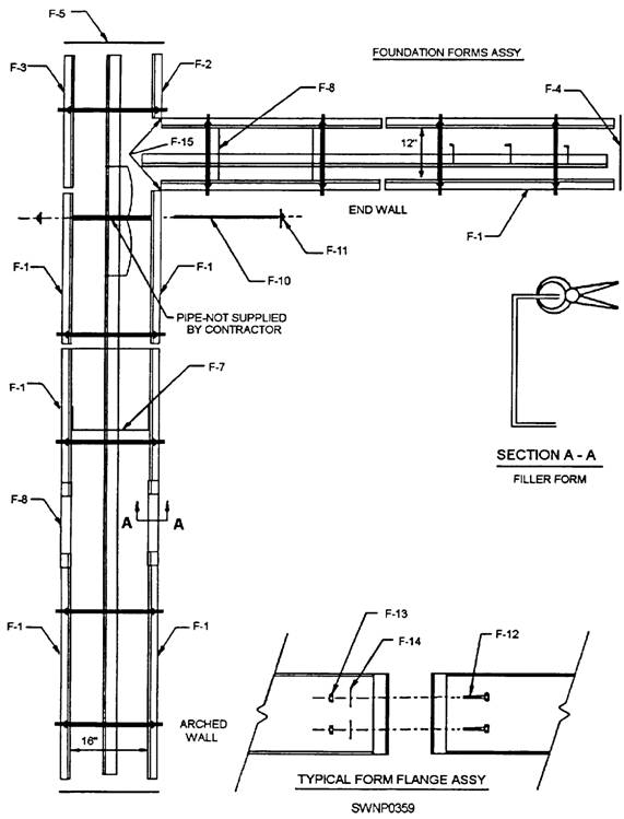
Figure 8-14.-Machinery placement calculations. Direction curved panels must be carried after being formed (F). Level area required to lay panels on the ground for seaming. Building will not be consistent if panels are not straight when seaming (G). Space required for crane operations (1-1). Foundations The design of the foundation for a K-span building depends on the size of the building, the existing soil conditions, and the wind load. `he foundations for the buildings are simple and easy to construct. With the even distribution of the load in a standard arch building, the size of the continuous strip footing is smaller and therefore more economical than foundations for more conventional buildings. The concrete forms and accessories provided are sufficient to form the foundations for a building 100 feet long by 50 feet wide. When a different configuration is required, forms are available from the manufacturer. The actual footing construction is based, as with all projects, on the plans and specifications. The location of the forms, the placement of the steel, and the psi (pounds per square inch) of the concrete are critical. The building panels are welded to the angle in the footer before the concrete is placed. Because of this operation, all of the aspects of the footer construction must be completely checked for alignment and squareness. Once concrete is placed, there is no way to correct errors. As mentioned above, forms are provided for the foundation. Using table 8-1 as a guide, figure 8-15 gives you a simple foundation layout by parts designation. As noted in figure 8-15, the cross pipes are not provided in the kit. They must be ordered when the project is being planned and estimated. Table 8-1.-Concrete Forms Included in Kit
Figure 8-15.-Simple form assembly. |
|
Privacy Statement - Press Release - Copyright Information. - Contact Us - Support Integrated Publishing |
|
|
Integrated Publishing, Inc. - A (SDVOSB) Service Disabled Veteran Owned Small Business
|