 |
||
|
|
||
| |||||||||||||||
|
|
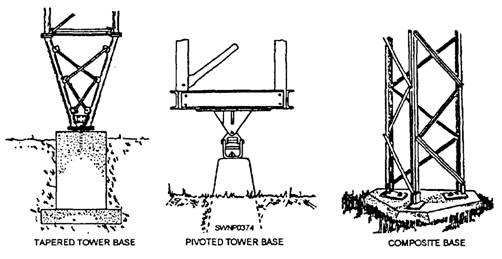
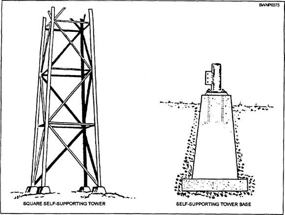
ANTENNA TOWERS Modem communications in different parts of the world between ships, shore stations, and aircraft, including the United States aerospace efforts, have required that transmitting and receiving facilities be erected all over the globe. Many times the Steelworkers from battalion detachments will be assigned to erect them. This section will describe some of the common communications antenna towers that are erected and the procedures for erecting them. GUYED TOWERS The most commonly used guyed towers are fabricated from steel in untapered sections 10 to 20 feet long. These constant dimensional sections are erected one above the other to form the desired height. Structural stability for this type of tower is provided by attaching guy wires from the tower to ground anchors. Base supports for guyed towers vary according to the type of tower to be installed. Three commonly used base supports are the tapered tower base, the pivoted tower base, and the composite base. All three are shown in figure 8-30. A tapered tower base concentrates the load from multiple tower legs to a small area on the foundation. The pivoted base is used primarily on lightweight structures for ease of tower erection. A composite base is generally used with heavier towers because it affords much greater supporting strength than the other two types. Sections for lightweight towers are usually assembled before delivery, to expedite final tower assembly, whereas heavier weight towers must be assembled completely in the field. Tower bracing should include diagonal bracing and horizontal struts in the plane of each tower face for the full tower height. FREESTANDING TOWERS Freestanding, or self-supporting, steel antenna towers are characterized by heavier construction than guyed towers and by a shape that tapers in toward the top from a wide base. Freestanding towers exert much greater weight-bearing pressure on foundations than most guyed towers. Consequent y, deeper foundations are required (because of the greater size, the weight, and the spread of tower legs) to provide sufficient resistance to the uplift. Each leg of a freestanding tower must be supported by an individual foundation. Figure 8-31 shows a typical individual foundation for a freestanding tower, and figure 8-32 shows a foundation plan for a triangular steel freestanding tower. Bracing and material specifications for these towers are the same as for guyed towers. TOWER ASSEMBLY Advance planning for tower assembly and erection is essential for completion of the project safely and correctly. Both the installation plan and the manufacturers' instructions should be studied to gain a complete understanding of the tower assembly and erection methods to be used. The following general procedures and practices should be observed for the assembly and erection of towers: 1. Assemble the tower sections on well-leveled supports to avoid building in twists or other deviations. Any such deviations in one section will be magnified by the number of sections in the complete assembly.
Figure 8-30.-Base support for guyed towers.
Figure 8-31.-Square self-supporting tower and base. 2. Check all of the surface areas for proper preservation. Cover all of the holes and dents in galvanized materials with sinc chromate or another acceptable preservative to prevent deterioration. 3. When high-strength bolts are used in a tower assembly, place a hardened steel washer under the nut or bolt head whichever is to be turned. Care must be exercised not to exceed the maximum torque limit of the bolt. Maximum torque values of several different sizes and types of bolts commonly used in antenna towers are listed in table 8-2. |
|
Privacy Statement - Press Release - Copyright Information. - Contact Us - Support Integrated Publishing |