|
||
|
|
||
| |||||||||||||||
|
|
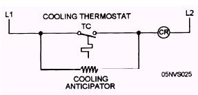
Anticipators One component that enhances the operation of a thermostat is an anticipator. Anticipators are of two types-heating and cooling. The heating anticipator produces false heat in a thermostat to prevent extreme temperature changes within a space. The false heat created by resistance increases the thermostat rate of response. Basically, the thermostat receives false heat which shuts down the heating source before the thermostat reaches the desired temperature. This action reduces overshooting and is economically efficient. The heating source shuts off and the blower continues to run using the heat transferred from the surface of the furnace and ductwork. When adjusting a heating anticipator, you must set the anticipator resistance to match the current rating of the primary control. The cooling anticipator adds false heat to the thermostat bimetal element the same way as a heating anticipator. Unlike the heating anticipator, cooling anticipators are not adjustable; they are sized by the manufacturer of the thermostat. The cooling anticipator is placed in parallel with the cooling contacts. By studying figure 14-20(D), you can see that the cooling anticipator is energized when the unit is in the OFF cycle (thermostat contacts open). The small amount of heat produced by the resistance heat closes the TC before the actual temperature in the space reaches the thermostat cut-in setting. This action allows the unit to start removing heat before the temperature in the space climbs above the desired temperature. When the cooling
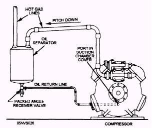
Figure 14-20(D).-Cooling anticipator. thermostat contacts close, the current flow through the anticipator is insignificant because the contacts of the thermostat offer less resistance to current flow than the anticipator resistance, so the anticipator is de-energized. Figure 14-21 shows a schematic piping diagram of a typical commercial refrigeration REFRIGERANT LINES AND PIPING system. This system has a roof-mounted air-cooled condenser and two motor com-Because of the progress made in this field, pressors. Each motor compressor has a construction has become much simpler. Since suction and a liquid header and is connected precharged lines are in everyday use, the to six refrigerant lines. A detailed view of an problems of installation are being eliminated. oil separator installation is shown in figure 14-22. However, pay particular attention to neatness and cleanliness when you are installing support brackets (hangers) and insulation.
Figure 14-22.-Installation of an oil separator.
Figure 14-21.-Schematic piping diagram for a commercial refrigeration system.
|
|
Privacy Statement - Press Release - Copyright Information. - Contact Us - Support Integrated Publishing |