|
||
|
|
||
| |||||||||||||||
|
|
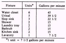
WATER SUPPLY SYSTEMS After the pipe runs and fittings are located on a print or drawing, the size, quantity, and joining requirements of the pipe must be determined. When a plumbing print is available for the job, it will contain this information. If there is no blueprint, you must determine these requirements yourself. The quantity of pipe required and the number and types of fittings you intend to use Table 7-8.-Fixture Demand
Table 7-7.-Size of Horizontal Building Storm Drains and Building Storm Sewers
are easily determined by tracing the layout of the water supply system as drawn in a print or sketch. Determining the size pipe you will require to meet the fixture demand of a facility is more complicated and will be discussed in this section. Sizing Cold-Water Supply Systems Some factors that affect the size of the water service in a plumbing system are the types of flush device used on the fixtures, the pressure of the water supply in pounds per square inch (psi), the length of the pipe in the building, the number and kind of fixtures installed, and the number of fixtures used at any given time. The stream of water in a pipe is made up of a series of layers moving at different speeds with the center layer moving the fastest. The resistance to flow is called pipe friction and causes a drop in pressure of the water flowing through the pipe. Friction loss may be overcome by supplying water at greater pressure than would normally be required or by increasing the size of the pipe. The two most important things to consider are the maximum fixture demand and the factor of simultaneous fixture use. The maximum fixture demand in gallons is the total amount of water that would be needed to supply all fixtures if they were being used at the same time for 1 minute. Since it is very unlikely that all fixtures would be turned on at the same time, a probable percentage of the fixtures in use at any given time must be found. This is the factor of simultaneous use. The more fixtures in a building, the smaller the possibility that all will be used at the same time. Therefore, simultaneous use factors decrease as the number of fixtures increase. To estimate the maximum fixture demand in gallons, the number and type of all fixtures in the completed plumbing system must be known. Table 7-8 is used to obtain the maximum fixture demand. For example, assume a plumbing system consists of three urinals, two water closets, one slop sink, two shower stalls, one kitchen sink, one laundry tray, and four lavatories. From table 7-8 a maximum fixture demand of 321 gallons per minute (gpm) can be figured. Normally only a small percentage of fixtures would be used at the same time, so the maximum fixture demand is reduced by applying the factor of simultaneous use. The factor of simultaneous use, also called the probable demand, is only an estimate. Table 7-9 gives data for making an estimate of probable demand. When using this table, take the actual number of fixtures installed, not the fixture unit value. For example, five fixtures would have a probable demand of about 50 percent, while 45 fixtures would have a probable demand of about 25 percent. When a table showing the factors of simultaneous use is not available, a practical way of figuring the probable demand is 30 percent of the maximum fixture demand in gallons. Many factors affect the flow of water through pipes resulting in a loss of water pressure. Difficult calculations are required to consider all the factors involved that may cause a loss of water pressure. These calculations are beyond the range of this manual. For simple systems, approximate figures are acceptable for most plumbing installations. Table 7-10 (for galvanized iron pipe) and table 7-11 (for copper tubing) may be used with the maximum fixture demand and the factor of simultaneous use to find the correct size of pipe for water-service lines. The minimum practical size for a water-service line is 3/4 inch. This size should be used even when calculations show that a smaller size could be used. To continue the example above, the 14 fixtures would have a factor of simultaneous use of about 35 percent. Since the maximum fixture demand was 321 gpm, the water-service line must have a capacity of 35 percent of 321, or 112 gpm. Assuming a length of pipe 60 feet long and a pressure at the main of 40 psi, table 7-10 or 7-11 shows that either a 1 1/2-inch galvanized iron or a 1 1/2-inch copper tubing water-service line would be large enough for the example fixture demand. |
|
Privacy Statement - Press Release - Copyright Information. - Contact Us - Support Integrated Publishing |
|
|
Integrated Publishing, Inc. - A (SDVOSB) Service Disabled Veteran Owned Small Business
|