Custom Search
|
|
  |
|
|
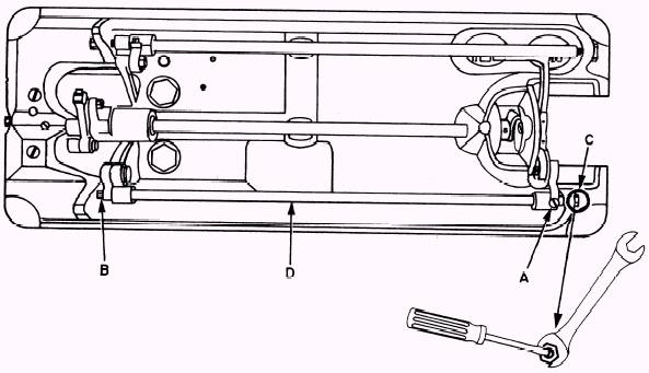
Setting the Presser Bar Turn the balance wheel until the feed dogs are just below the top of the throat plate. Loosen the presser bar guide lever setscrew (figure 4-16 [C]). Push the presser firmly against the throat plate, aligning the slot between the toes of the presser foot with the hole in the throat plate. Tighten the presser bar guide lever setscrew. This completes
Figure 4-18.\Centering feeding action.
Figure 4-19.\Feed-driving eccentric. the timing and adjustment procedures for the 31-15 sewing machine. DISASSEMBLY AND REASSEMBLY OF THE 1ll W 155 SEWING MACHINE You probably will never need to take the lll W 155 class sewing machine completely apart, but you may need to replace some parts. Therefore, you need to know the procedures for disassembling and reassembling the 111 W 155 sewing machine. The following are some helpful hints that you should remember while working on disassembly and reassembly of any sewing machine: . All sewing machine screws have a casehardened surface, which must be removed by grinding should it become necessary to use an easyout to remove the screw. . Using grinding compound is recommended when you are replacing parts that attach to a shaft. Place a small amount of grinding compound on the shaft and rotate the part on the shaft until it moves freely. (Remove all grinding compound before you reassemble the parts.) l Oiling is a must in the reassembly of parts. A generous amount of 10W mineral oil is justified when you are replacing parts. . There is one screw (thread take-up lever retaining screw) on the drop-feed type of sewing machine that has a left-hand thread. It is found in the face of the machine. This screw is removed by turning it clockwise. # DISASSEMBLY In this section we discuss the purpose of each part of the 111 W 155 sewing machine and the disassembly and reassembly of each part. Before disassembling any sewing machine, you should select and clean an area that will allow you to work on your project with a minimum of interruptions. Select your tools, cleaning solvents, and a parts breakdown list; then you are ready to begin your project. Arm Cap The arm cap (figure 4-2 [B]) permits inspection of the mechanism of the arm. The arm mechanism is exposed when the arm cap is moved to one side or the other. Remove the arm cap by unscrewing the holding screw and spring washer that attach it to the machine arm; then lift the arm cap from the machine. Faceplate The faceplate (figure 4-2 [F]) permits inspection and minor adjustment of the parts in the machine face. The mechanism of the machine face is exposed when the faceplate is moved to one side or the other. Remove the faceplate by removing the thumbscrew at the top of the plate; then move the plate slightly to the left to clear the metal projection at the lower left corner and lift the faceplate from the machine. Knee Lifter Lifting Lever Hinge Screw The knee lifter lifting lever hinge screw (figure 4-11 [E]) acts as a hinging point for the knee lifter lifting lever. It is removed from the machine by unscrewing it. Knee Lifter Lifting Lever The knee lifter lifting lever (figure 4-11 [F]) acts as an extending arm that attaches the presser bar lifting releasing lever bracket to the knee lifter lifting lever. It carries the motion from the knee lifter lifting lever to the presser bar lifting releasing lever bracket. Remove the knee lifter lifting lever by grasping and moving it outward from the machine. Presser Bar Spring Support Screw The presser bar spring-support screw (figure 4-11 [G]) acts as a suspension point for the presser bar spring. The screw is loosened approximately one-fourth of an inch to allow for the removal of the presser bar spring. Do not remove the presser bar spring-support screw from the machine. Presser Bar Spring The presser bar spring (figure 4-11 [H]) applies a constant pressure to the presser bar. To remove the presser bar spring from the machine, lower the presser feet and then grasp the underside of the spring as near the support screw as possible with two fingers of one hand over two fingers of the other hand. Now slide the spring outward to the head of the support screw, rolling the spring up and out of the machine. Presser Bar Lifting Releasing Lever Bracket Guide Screw The presser bar lifting releasing lever bracket guide screw, (figure 4-11 [1]) acts as a track and guide for the presser bar lifting releasing lever bracket. Remove the presser bar lifting releasing lever bracket guide screw by unscrewing it from the machine. Presser Bar Position Guide The presser bar position guide (figure 4-7 [D]) acts as a track to control the presser bar position guide lever. To remove the presser bar position guide, you should loosen (six turns) the spline screw on the rear side nearest the face of the machine and push the guide through the recess at the top of the machine head. Presser Bar Position Guide Lever The presser bar position guide lever is used to align the presser foot, and it operates in the slot of the presser bar guide. NOTE: The presser bar position guide does not screw out. Loosen the pinch screw on the presser bar position guide lever (figure 4-11 [K]) by inserting the screwdriver into the opening on the rear side of the machine head. This is necessary to allow movement of the presser bar for the removal of attached parts. Alternating Presser Foot The alternating presser foot is the rear presser foot and holds the material in place while the needle and front presser foot move forward making another bight. To remove the rear presser foot, you unscrew the presser foot position screw on the left side of the presser bar. Raise the presser bar to its highest position and remove the foot from the rear. Presser Bar Spring Bracket The presser bar spring bracket (figure 4-7 [E]) transfers the tension from the presser bar spring to the presser bar. To loosen the presser bar spring bracket from the presser bar, insert the screwdriver through the lower opening provided in the back of the face of the machine. Loosen the presser bar lifting bracket pinch screw (figure 4-11 [C]). Remove the presser bar lifting bell crank retaining screw and lifting bell crank (figure 4-7 [F] and [G]). Now remove the presser bar (figure 4-7 [M]) in a slow upward motion. |
|
|
|