Custom Search
|
|
  |
|
|
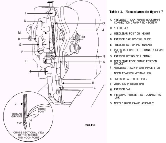
Tilt the machine down and place the long curved end of the presser bar spring through the opening in the back of the machine head and into the slot in the presser bar spring bracket. Place the small curved end over the presser bar spring-support screw. Push it down and under the presser spring-regulating screw. Tighten the presser bar spring-support screw. Install the large guide screw. NOTE: Preadjust the spring bracket with the presser foot firmly on the throat plate, and make sure the foot is straight. Raise the presser bar spring bracket about one-eighth inch and tighten the pinch screw. . At this time, adjust the presser bar guide lever one-quarter inch up from the bottom of the guide as in figure 4-7 (K). . Tighten the pinch screw (figure 4-11 [B]). Front Presser Bar Connecting Link Place the large end of the line on the front presser bar stud. Bell Crank The bell crank has three attachment points: (1) the bell crank connection link, (2) the lifting lever bell crank stud, and (3) the front presser bar connecting link stud. All three must be engaged at the same time. Install and tighten the retaining screw. Front Presser Foot and Presser Pressure-Regulating Thumbscrew Install the foot on the front presser foot and the regulating screw on the top of the face. Knee Lifter Lifting Lever Replace the knee lifter lifting lever so that the slotted end fits over the projection on the knee lifter connection lever. The projection on the curved end of the knee lifter lifting lever fits under the presser bar releasing bracket. Knee Lifter Lifting Lever Hinge Screw Align the hole in the knee lifter lifting lever with the corresponding hole in the machine arm; then insert the hinge screw. Make certain the screw, including the shoulder, is fully inserted. Faceplate Insert the thumbscrew and secure it. Arm Cap Replace the arm cap and the spring washer on the machine arm and screw them in place. This completes the reassembly of the 111 W 155 sewing machine. It will be necessary to make a few minor adjustments or retime this machine. Timing and adjustment are covered at the beginning of this chapter.
Table 4-1.\Nomenclature for figure 4-6
Figure 4-6.\Bottom view of Model 225.
Figure 4-7.\Face view of Model 225
Table 4-3.\Nomenclature for figure 4-11
Figure 4-11.\Rear view Model 225. |
|
|
|