Custom Search
|
|
  |
|
|
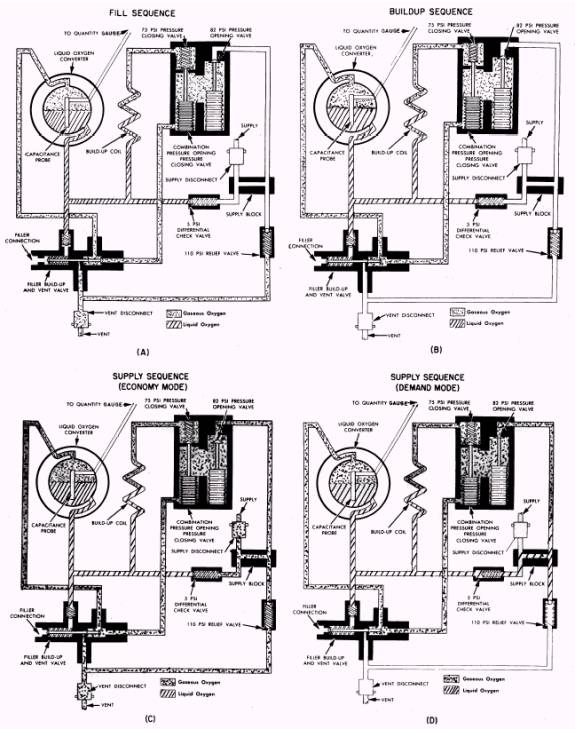
SYSTEM OPERATION The LOX system shown in figure 4-7 is an example of a typical system. This system converts LOX to gaseous oxygen and delivers it to the crew. The oxygen source of this system is a supply of LOX stored in a 10-liter converter. System pressure is maintained at 75 to 110 psi by a pressure control valve and a pressure relief valve. The converter in this system is installed in an aft equipment compartment. Through a process of controlled evaporation within the converter assembly, LOX is converted to gaseous oxygen as required by the occupant of the aircraft. The oxygen is delivered to the pilot after being warmed to a safe breathing temperature in the heat exchanger. The flow of oxygen is controlled in the cockpit by the shutoff valve. The major part of the operation of the LOX system is controlled automatically by the units that make up the converter assembly. The LOX converter has three sequences of operation- fill, buildup, and supply (fig. 4-15). In the supply sequence, the converter alternates between the economy and demand modes of operation. Fill Sequence The fill sequence begins automatically when the servicing trailer hose filler nozzle is connected to the filler port on the filler, buildup, and vent valve. The hose nozzle, when attached to the fill valve, actuates a plunger within the valve, which places the valve in the fill and vent condition (fig. 4-15, fill sequence, view A). The valve, when in this position, provides an opening from the top of the converter to the atmosphere. This open-ing is used to vent gaseous oxygen during filling and liquid oxygen after the converter is full. During transfer, liquid oxygen flows into the converter through a passage located in the bottom of the converter. This arrangement allows gaseous oxygen to vent through the converter top as it is being displaced by liquid flow in the bottom. When the converter is full, liquid flows overboard through the vent line, giving an indication that the converter is full. Removal of the filler hose nozzle from the fill valve automatically places the converter in the buildup sequence. Buildup Sequence The buildup sequence (fig. 4-15, buildup sequence, view B) begins when the filler hose is removed from the converter. This sequence provides for rapid pressure buildup to system operating pressure. During this sequence, LOX from the converter fills the buildup coil by gravity feed. Liquid in the coil absorbs heat from the ambient air around the coil and vaporizes, causing the pressure to build up. The gaseous oxygen formed in the coil then circulates through the pressure closing valve and back to the top of the converter. This causes more liquid to flow into the buildup coil. This circulation continues to build up pressure until approximately 75 psi is reached. At this pressure, the pressure closing valve is forced closed. Pressure continues to buildup within the system at a slower rate, and at approximately 82 psi, the pressure opening valve opens. When this occurs, oxygen is available at the supply outlet. A pressure relief valve, which is set at approximately 110 psi,
Figure 4-15.- Liquid oxygen converter operation. is installed in the converter system to relieve excessive pressure. Supply Sequence The supply sequence of the liquid oxygen system consists of two modes of operation- the economy mode, in which gaseous oxygen is fed from the converter, and the demand mode, in which oxygen flows from the converter as a liquid and vaporizes to a gas in the feed line. In the economy mode of operation (fig. 4-15, supply sequence, view C), limited demand upon the system allows the converter to supply gaseous oxygen directly as a result of drawing off the gaseous oxygen stored within the top of the converter. At approximately 82 psi, the pressure opening valve unseats and allows gaseous oxygen to flow from the converter to the supply system. Oxygen then flows from the upper (gas) portion of the converter, rather than the liquid side. When the amount of oxygen demanded by the crew exceeds the supply capabilities of the economy mode, the pressure opening valve closes. As the crew continues to draw upon the oxygen supply, the supply system pressure becomes lower than that of the converter. When a pressure differential of 5 psi occurs, the differential check valve opens (fig. 4-15, supply sequence, views C and D) and allows liquid oxygen to flow into the supply line, thus creating the demand mode. Converter pressure will build up while the system is operating in the demand mode. As the pressure again approaches 82 psi, the pressure opening valve will again unseat, switching the supply sequence back into the economy mode. The converter automatically switches itself back and forth between the economy and demand modes while supplying oxygen to the crew.
|
 |
|
|