Custom Search
|
|
  |
|
|
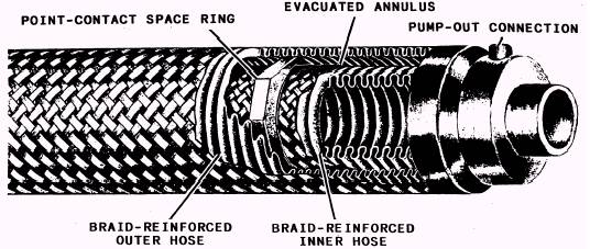
TRANSFER LINES Aside from certain large fixed facility piping, most LOX systems are made up of transfer lines- often segmented (in sections) for ease of demountability (reconnecting) so one transfer system can service several pieces of equipment. Generally, what is true for insulation of tanks is applicable to other similar equipment with the exception of transfer lines. Transfer lines are cooled and warmed many times during the course of a day. The liquid oxygen waste due to cooldown losses can be significant. A high vacuum insulated transfer line generally is best for quick, frequent transfers since no insulated cooldown mass is involved. To help reduce LOX waste due to cooldown of transfer lines, several wraps of multilayer insulation adds very little mass to the system, decreases the thermal radiation, and requires less vacuum (if any) in the insulation annulus. Transfer lines are most commonly constructed of bronze, stainless steel, or aluminum. In the case of vacuum-jacketed lines, annular spaces are necessary to prevent the inner liquid-bearing lines from touching the outer jacket wall. Low thermal conductivity materials are used for this purpose, and schemes are incorporated into the spacer design to provide only a small area contact wherever possible, since the heat influx must be kept low. Although rigid lines often are used in stationary facility piping installations and for some remountable applications, the predominant type for use in the field is corrugated flexible metal transfer hose (fig. 5-2). Flexible metal hose is somewhat more vulnerable to abuse than its rigid counterpart; therefore, it usually has a braided metallic covering or tough plastic sheath over the external corrugations. The high working pressure capability of the inner line requires the application of a strengthening braid over it as well. Even though such protection provides a degree of reinforcement to the hose, it should not be subjected to overpressurization in service since a bellowslike action still may be possible if the covering is not securely fastened at the end connections. High pressure expands the hose axially, causing it to grow by lengthening the distance between each corrugation, which makes the line less flexible. A vital consideration in the construction of all transfer lines is the matter of joints between line segments. Assuming that the transfer lines are vacuum-jacketed to the general region of the joint, the concern with the joint and the closure of the vacuum-jacket in close proximity to the joint is important. The transfer line connector/ coupling (bayonet coupling) in figure 5-3 is one of the better designs available today, and the most expensive. To safely and efficiently use transfer lines, several things must be remembered. NEVER trap liquid in a line between closed valves unless you are absolutely certain that some type of relief device is functionally associated with the inner
Figure 5-2.- Flexible metal transfer hose.
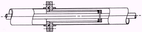
Figure 5-3.- Transfer line connector/ coupling. line. The reason is that as the LOX vaporizes, the vapors will warm, and excessive pressures may develop that can burst the conduit walls. For transfer efficiency, vacuum-jacketed lines with well-designed, low-heat input couplings are best for most uses. Unthinking use of two or three transfer sections coupled together where one could do the job wastes liquid and time. Several times as much line material has to be cooled down, and several times more heat transferring line surface area is contacted by the LOX. Additional heat influx means additional LOX vaporization; therefore, more liquid is needed to satisfy a given transfer demand.
|
|
|
|