Custom Search
|
|
  |
|
|
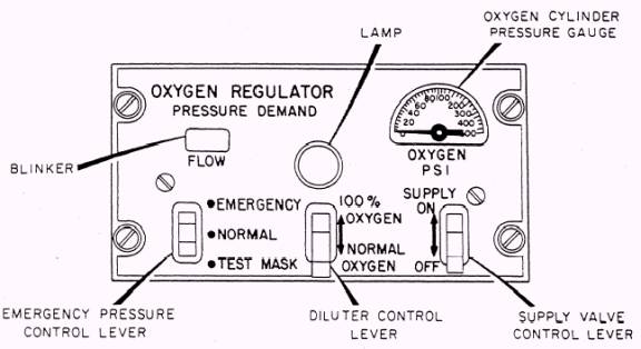
Aircraft-Mounted Oxygen Regulators The MD series regulator is being used in several multiplace naval aircraft. There are two types of regulators in this series- the MD-1 (low-pressure) and MD-2 (high-pressure). The only difference found in these regulators is operating pressure. The operating pressure of the MD-1 regulator is 50 to 500 psi. The pressure gauge reads 0 to 500 psi. The operating pressure of the MD-2 regulator is 50 to 2,000 psi. The pressure gauge reads 0 to 2,000 psi. The following controls and indicators are located on the front panel of the regulator (fig. 4-13). The small oblong-shaped window area on the left side of the panel marked FLOW indicates the flow of oxygen through the regulator by a visible blinking action. The pressure gauge is found on the upper right of the panel and indicates inlet pressure to the regulator. The regulator has three control levers. A supply valve controller lever, located on the lower right corner, is used to control the supply of oxygen to the regulator; a diluter control lever, located on the lower center of the panel, has two positions- 100% OXYGEN and NORMAL OXYGEN; an emergency pressure control lever, located on the lower left of the panel, has three positions- EMERGENCY, NORMAL, and TEST MASK, and with the deluter lever in the 100% OXYGEN position, the regulator delivers 100 percent oxygen upon inhalation by the user. In the NORMAL OXYGEN position, the regulator delivers a mixture of air and oxygen with the air content decreasing until a cabin altitude of approximately 30,000 feet is reached. Above this altitude, 100-percent oxygen is delivered to the user upon inhalation. With the emergency pressure control lever in the EMERGENCY position, the regulator delivers positive oxygen pressure to the outlet at altitudes when positive pressure is not automatically delivered. In the TEST MASK position, oxygen is delivered to the mask under pressure too high to breathe and is used for checking the fit of the mask. The switch must be in the NORMAL position to assure normal system operation. Refer to figure 4-14 for the operation of an MD type regulator. 1. Supply oxygen entering through the oxygen inlet (1) is filtered and passes through the manifold
Figure 4-13.- Regulator operating controls and indicators.
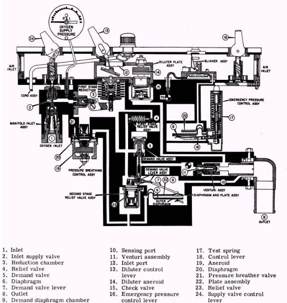
Figure 4-14.- MD regulator operational drawing. inlet assembly into the inlet supply valve (2), and 2. The reduction chamber incorporates the then into the first-stage reduction chamber (3) by first-stage relief valve assembly (4) to protect the action of the inlet supply valve control lever 24. regulate; against overpressures. The pressure of the flowing oxygen is registered 3. The demand valve assembly (5) is opened on the oxygen supply pressure gauge. when the pressure across demand outer diaphragm (6) forces the demand valve lever assembly (7) down. The pressure differential exists during the inhalation cycle of the user by creating a reduction in the pressure outlet (8). 4. Reduction in pressure at the pressure outlet is sensed in the demand diaphragm chamber (9) through the sensing port (10). 5 During periods of flow, the oxygen passes through the venturi assembly (11). At the venturi assembly, the flow of oxygen mixes with ambient air, which enters the regulator through the inlet ports (12). 6. The addition of ambient air to oxygen is controlled by the manual diluter control lever (13) and by the diluter aneroid assembly (14), which automatically produces a 100-percent oxygen concentration at altitudes above 32,000 feet. 7. The aneroid check valve assembly (15) prevents a flow of oxygen out through the inlet ports. 8. The emergency pressure control lever (16) applies force to the emergency pressure control test spring (17), which mechanically loads the emergency pressure diaphragm (25) through the control lever and center assembly (18). Mechanical loading of the emergency pressure diaphragm provides positive pressure at the regulator outlet. 9. Both automatic safety pressure and pressure breathing at altitudes above 30,000 feet are provided through pneumatic actuation of the aneroid assembly (19). This function begins near 27,000 feet altitude. The force exerted on the diaphragm assembly (20) by the aneroid assembly actuates the pressure breather valve assembly (21), and oxygen flows to the diaphragm and the plate assembly (22), which is pressure loaded by this volume of oxygen acting on the demand valve lever assembly to the extent that the positive pressure is built up at the pressure outlet as the altitude increases. 10. Additional safety is obtained through the inclusion of the second-stage relief valve assembly (23) in the regulator.
|
 |
|
|