Custom Search
|
|
  |
|
|
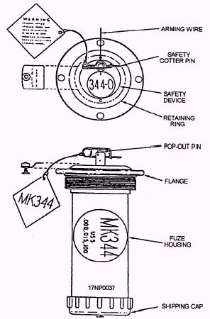
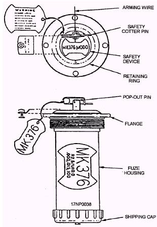
LEARNING OBJECTIVE: Identify the various types of electrical fuzes to include their physical description and functional operation. The Mk 344 (fig. 1-9) and Mk 376 (fig. 1-10) electric bomb fuzes provide an all-electric capability for the Mk 80 (series) bombs with either conical or retarding fins, thermally protected bombs, and laser-guided bombs (LGB). Electric fuzes require an electric pulse from the aircraft fuze function control (FFC) system.
Figure 1-9.-Mk 344 Mods 0 and 1 electric fuzes.
Figure 1-10.-Mk 376 Mod 0 electric fuze. The FFC gives in-flight selection of function delay and arming delay times. The Mk 344 and 376 fuzes are used with the Mk 43 target-detecting device for airburst capability. They may also be used with mechanical nose fuzes for additional fuzing options. DESCRIPTION The Mk 344 Mod 0 and Mod 1 and Mk 376 Mod 0 electric tail fuzes are detonator safe. The boosters contain 4.3 ounces of tetryl explosive. They are classified HERO SAFE, and no unusual RADHAZ precautions are required under normal operating conditions. The Mk 344 Mod 0 and Mod 1 fuzes are identical, except that the retard sensor has been removed from the Mod 1. The Mk 344 Mod 0 or Mod 1 is not used in the retarded mode of delivery and should never be configured for this type of delivery. The fuzes are similar in appearance, but they are readily identifiable by decals. Four discreet dc voltages for in-flight selection of functioning delay times are used in the Mk 344 Mods and Mk 376 fuzes. Arming delay times are automatically selected by the Mk 31 safety device. MK 31 SAFETY DEVICE The Mk 31 safety device is used to adapt the fuze to the fuze well of the bomb, provide mechanical safing of the fuze and unlock the timer-decelerometer. The safety device contains a pop-out pin that locks the fuze in an unarmed condition. The spring-loaded pin is held in the safe position by either a safety cotter pin or an arming wire. When the weapon is released from the aircraft, the arming wire is pulled from the pop-out pin, allowing the pin to pop out, unlock the decelerometer, thus initiating the arming time. When using the Mk 344 Mod 0 or Mod 1 fuze, the arming is completed 5.5 seconds after the pop-out pin is released. For the Mk 376 fuze, arming is completed 10.0 seconds after release from the aircraft if the free-fall mode of delivery is used. If the Mk 31 safety device senses weapon deceleration (Snakeye fins open), the internal circuits of the fuze are switched, and the fuze becomes armed in 2.6 seconds. The quicker arming time is required to ensure the fuze is fully armed for low-altitude delivery. If deceleration is not sensed by 2.6 seconds, the fuze arming delay continues to the 10.0-second arming time. The following description applies specifically to the Mk 376 fuze. However, the Mk 344 fuze operates identically to the Mk 376, except that it is operationally restricted to the unretarded (5.5-second delay) delivery mode only. Two arming delays are used in the Mk 376 fuze-2.6 seconds for retarded delivery and 10.0 seconds for unretarded delivery. The appropriate arming delay is automatically selected by the fuze according to the actual delivery mode of the weapon. That is, if the weapon does not retard, whether intentionally or unintentionally, the fuze automatically provides a 10.0-second arming delay. At release, the arming wire is withdrawn and a charging voltage (+300, +195, -195, or -300 Vdc) is applied to the fuze. The pilot selects the voltage in flight by the fuze function control set located in the cockpit. The fuze polarity and level of the fuze charging voltage is important only with respect to functioning delay. Arming is the same in any case. A regulator in the fuze converts the applied voltage to the required level and polarity. It is then applied to the energy storage unit and the 2.6-second timer. If the weapon decelerates, the Mk 31 safety device senses the deceleration and causes the retard switch to close. At 2.6 seconds, the timer completes its cycle and transfers the voltage to the rotor-actuating bellows. The bellows operate and turn the rotor to the armed position. If the weapon does not decelerate, the retard switch does not close. The 2.6-second timer continues to run. At 3.8 seconds, the Mk 31 safety device causes the voltage to transfer to the input of the rotor-actuating bellows. At 10.0 seconds, the bellows operates and turns the rotor to the armed position. |
 |
|
|