Custom Search
|
|
  |
|
|
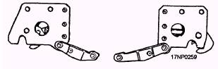
CHAPTER 10 SUSPENSION, ARMING, AND RELEASING EQUIPMENT The Navy uses complex suspension, arming, and releasing devices in combat aircraft and weapons. The high speed and performance of potential targets and our own aircraft require the electronic operation of suspension, arming, and releasing equipment. The equipment covered in this chapter is part of the aircraft search or kill stores systems. Generally, these devices operate electrically and are controlled by aircraft electrical circuits. They are actuated manually by a hand switch or automatically by a circuit-closing device in the system. BOMB RACKS LEARNING OBJECTIVE: Identify the purpose and use of bomb racks. Recognize the bomb racks used for various configurations, and identify the operation of bomb racks to include electrical and manual release and arming. Aircraft bombs, torpedoes, mines, and other stores are suspended internally or externally from the aircraft by bomb racks. Bomb racks carry, arm, and release stores. AERO 65A SERIES BOMB RACK Aero 65A bomb racks are used to suspend, selectively arm, and release 1,000-pound class stores. These stores have suspension hooks spaced 14 inches apart. When used with the Aero 1A adapter assembly, you can suspend weapons/stores with lugs spaced 30 inches apart and weighing up to 2,000 pounds. Some Aero 65A bomb rack models are pylon mounted to the wing stations of the P-3C aircraft. Aero 65A series bomb racks (fig. 10-1) consist of a frame. Mounted inside the frame are an electrical release unit, two arming solenoids, two hook assemblies (spaced 14 inches apart), a manual release cable assembly, a release linkage assembly, a hook tie linkage assembly, and a cable assembly. The frame is a U-shaped, alloy steel channel. It has holes at both ends so you can mount it in an aircraft or attach Aero 1A adapter assemblies. Access holes in the frame let you visually verify that the hook closing is latched. These holes let you insert the safety pin, cocking lever, and hoist bracket. The electrical release unit is a spring-loaded plunger. It is mechanically cocked and electrically released to provide the force that initiates hook release.
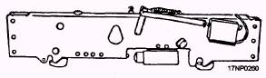
Figure 10-1.-Cutaway view of a typical Aero 65A bomb rack. 10-1 The release unit bolts to the bottom of the bomb rack frame near the center. Before the hook tie linkage is cocked, you must cock the release unit plunger. The electrical cable assembly supplies 28 volts of dc through a four-pin male connector. Three types of electrical release units are used-the Aero 7B release unit, the Aero 7B-1 release unit, and the linear electromechanical actuator (LEMA). The external difference between the Aero 7B and Aero 7B-1 is the two-piece plunger barrel on the Aero 7B-1. The LEMA is similar to the Aero 7B-1 release unit. You can identify it by the decal located on the release unit. There are two arming solenoids at the bottom of the bomb rack frame, slightly forward of the center. The arming units are electrically controlled and mechanically operated continuous-duty solenoids. They provide fully selectable arming for nose, tail, or nose and tail when weapons are armed by arming wires. Arming is selectable in flight by the pilot. The pilot also has a safe selection, which does not energize the arming solenoids. The weapon/store is suspended from two suspension hook assemblies protruding from the bottom of the bomb rack. Each hook latches independently. You mount it in the bomb rack frame by using a pivot pin. Each hook is made from chrome-plated steel or stainless steel. It has a bushing in the pivot hole, a latch pin engaging the hook tie linkage to latch the hook, and a threaded spring stud to attach a spring to preload the hook in the open position. A manual release cable assembly is located at the center of the bomb rack. It consists of a pull ring and a cable extending for the depth of the bomb rack. The cable is attached to a manual-release link assembly or a manual-release lever located at the bottom of the bomb reck. When the pull ring is connected to the aircraft's externally routed manual-release cable, the pilot has the option of manual release. The release-linkage assembly, located at the center of the bomb rack, contains a release bell crank and bell crank link, a sear link, and two attaching pins. The hook tie linkage assembly extends end-to-end on the bomb rack. It contains a bumper and four moving parts-two latches and two links, which are set between two hook tie links. The tie linkage latch link contains cutouts so you can insert the lock-link assembly and the screw holding the latching pin in place. The electrical cable assembly consists of five leads. Two leads are attached to the solenoids. The remaining leads are routed along the top inside surface of the bomb rack. They terminate in a female connector that mates with the release unit. There are two accessories for the Aero 65A bomb rack-an Aero 1A adapter assembly and a safety interlock mechanism. These accessories are issued as required. They do not come with the bomb rack. Aero 1A Adapter Assembly The Aero 1A adapter assembly (fig. 10-2) lets you load and carry weapons/stores that have suspension lugs spaced 30 inches apart and weigh up to 2,000 pounds. When you install two Aero lA adapter assemblies on the bomb rack (one on either end), the adapter assemblies let you attach the bomb rack to the aircraft pylon assembly. The Aero 1A adapter linkage attaches to the bomb rack. The movement of the Aero 1A adapter suspension hooks corresponds to the movement of the bomb rack suspension hooks. If you need more information about the Aero 1A adapter assembly, refer to Bomb Rack Adapter Assembly Aero 1A, NAVAIR 11-5E-17. Safety Interlock Mechanism The safety interlock mechanism is an in-flight, operable bomb-rack lock (IFOBRL) (fig. 10-3). It provides additional safety when the aircraft carries
Figure 10-2.-Aero 1A bomb rack adapter assembly.
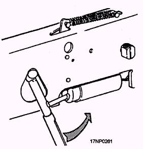
Figure 10-3.-In-fligbt operable bomb rack lock (IFOBRL),
Figure 10-4.-Cocking procedure. special stores. The Aero 65A series bomb racks use a special stores conversion kit installation. The safety interlock mechanism has a linear electromechanical actuator. When energized, the actuator unlocks the safety interlock mechanism and permits release of the store. You can find more information on the IFOBRL by referring to the applicable aircraft maintenance manual. |
 |
|
|