Custom Search
|
|
  |
|
|
Learning Objective: Identify differential design variations. Describe the principles of the limited slip differential. Explain basic service and repair of a differential. Explain the adjustment of the ring and pinion gears. Another important unit in the power train is the differential, which is driven by the final drive. The differential is located between the axles and permits one axle to turn at a different speed from that of the other. The variations in axle speed are necessary when a vehicle rounds a corner or travels over uneven ground. At the same time, the differential transmits engine torque to the drive axles. The drive axles are on a rotational axis that is 90 degrees different than the rotational axis of the drive shaft. DIFFERENTIAL CONSTRUCTION Differential Carrier REMOVABLE TYPE- a carrier that bolts to the front of the axle housing. Stud bolts are installed in the housing to provide proper carrier alignment. A gasket is installed between the carrier and the housing to prevent leakage.
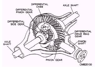
Figure 5-12.- Conventional differential. INTEGRAL TYPE- a carrier that is constructed as part of the axle housing. A stamped metal or cast aluminum cover bolts to the rear of the carrier for inspection of the gears. Differential Case Pinion Gear The pinion gear is mounted on tapered roller bearings that allow the pinion gear to move freely on the carrier. Either a crushable sleeve or shims are used to preload the pinion gear bearings. Some differentials use a pinion pilot bearing that supports the extreme inner end of the pinion gear. The pinion pilot bearing assists the tapered roller bearings in supporting the pinion gear during periods of heavy loads. Ring Gear The ring and pinion gears are a matched set. They are lapped (meshed and spun together with an abrasive compound on the teeth) at the factory. Then one tooth on each gear is marked to show the correct teeth engagement. Lapping produces quieter operation and assures longer gear life. Spider Gears |
 |
|
|