Custom Search
|
|
  |
|
|
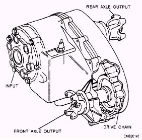
Learning Objective: Explain the operation of a transfer case. Explain basic service operations on a transfer case. Transfer cases are used in off-road vehicles to divide engine torque between the front and rear driving axles. The transfer case also allows the front driving axle to be disengaged, which is necessary to prevent undue drive line component wear during highway use. Another purpose of the transfer case is to move the drive shaft for the front driving axle off to the side so that it can clear the engine. This arrangement is necessary to allow adequate ground clearance and to allow the body of the vehicle to remain at a practical height. Figure 5-27 shows a typical drive line arrangement with a transfer case. CONVENTIONAL TRANSFER CASE
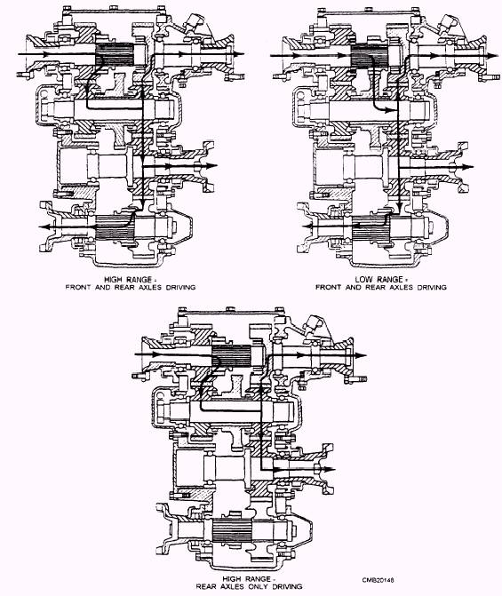
Figure 5-27.- Typical drive line arrangement with a transfer case. The conventional transfer case provides a high and low final drive gear range in the same manner as an auxiliary transmission. In most cases, the shifting is accomplished through a sliding dog clutch, and shifting must be done while the vehicle is not moving. Typical operation of a conventional two-speed transfer case is as follows: High Range (fig. 5-30)-
When driving the front and rear axles in the high range (1: 1 gear ratio), the external teeth of the sliding gear
Figure 5-29.- Typical conventional transfer case using chain drive.
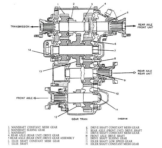
Figure 5-28.- Cross-section of a typical conventional transfer case.
Figure 5-30.- Transfer case power flow. (splined to the transmission main shaft) are in mesh with the internal teeth on the constant mesh gear, mounted on the transmission main shaft. Likewise, the external teeth of the front axle sliding gear are in mesh with the internal teeth of the constant mesh gear or the sliding clutches are engaged. Disengagement of the drive to the front axle is accomplished by shifting the sliding gear on the front axle main shaft out of mesh with the constant mesh gear, permitting the latter to roll free on the shaft or sliding the clutches out of mesh. Low Range (fig. 5-29)- When using the low range in the transfer case, the sliding gear on the transmission main shaft is disengaged from the constant mesh gear and engaged with the idler gear on the idler shaft. This design reduces the speed by having the sliding gear mesh with the larger idler gear. The shifting linkage on some vehicles is arranged so shifting into low range is possible only when the drive to the front axle is engaged. This design prevents the operator from applying maximum torque to the rear drive only, which can cause damage. |
 |
|
|