Custom Search
|
|
  |
|
|
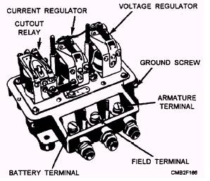
The fields of the generator depend upon the current from the armature of the generator for magnetization. Because the current developed by the generator increases in direct proportion to its speed, the fields become stronger as the speed increases and, correspondingly, the armature generates more current. The extreme variations in speed of the automotive engine make it necessary to regulate output of the generator to prevent excessive current or voltage overload. On the average unit of CESE, a charging current in excess of 12 to 15 amperes is harmful to a fully charged battery if continued for too long. Regulators are of two types, functioning to regulate either voltage or current. The voltage regulator regulates the voltage in the electric system and prevents excessive voltage, which can cause damage to the electric units and overcharge the battery. The current regulator is a current limiter; it prevents the generator output from increasing beyond the rated output of the generator. Regulation of voltage only might be satisfactory from the standpoint of the battery; however, if the battery were badly discharged or if a heavy electrical load were connected, the heavy current might overload itself to supply the heavy current demand. Therefore, both current and voltage controls are used in a charging system. In most applications, a regulator assembly consists of a cutout relay, current regulator, and voltage regulator (fig. 2-13). Each unit contains a separate core, coil, and set of contacts. The regulator assembly provides full control of the shunt-type generator under all conditions. Either the current regulator or the voltage regulator may be operating at any one time, but in no case do they both operate at the same time. When the electric load requirements are high and the battery is low, the current regulator will operate to prevent the generator output from exceeding its safe maximum. In this case, the voltage is not sufficient to cause the voltage regulator to operate. But if the load requirements are reduced or the battery begins to come up to charge, the line voltage will increase to a value sufficient to cause the voltage regulator to operate. When this happens, the generator output is reduced; it is no longer sufficiently high to cause the current regulator to operate. All regulation is then dependent on the voltage regulator. Figure 2-14 shows a schematic wiring diagram of a typical dc charging circuit. In this circuit, two resistances are connected in
Figure 2-13.- Regulator assembly with cover removed. parallel into the generator field circuit when the current regulator points open. This provides a low value of resistance, which is sufficient to prevent the generator output from exceeding its safe maximum. When the voltage regulator contact points open, only one resistance is inserted into the generator field circuit, and this provides a higher value of resistance. The voltage regulator must employ a higher resistance because it must reduce the generator output as it operates, and it requires more resistance to reduce the output than merely to prevent the output from going beyond the safe maximum of the generator. For some special applications, you may find a combined current-voltage regulator. In this case, the regulators are combined in a single unit. The regulator assembly will consist of two (regulator and circuit breaker) instead of three units. The regulators just described are known as electromagnetic vibrating-contact regulators. The points on the armatures of the regulators may open and close as many as 300 times in one second to achieve the desired regulation. The transistor type regulator is being used in late model equipment. This regulator has no moving parts. It consists of transistors, diodes, condensers, and resistors. Some models have two filter condensers, while others have only one. Adjustments are provided on some types of regulators and should be made only with the use of the manufacturer's instructions and the recommended testing equipment. TRIAL AND ERROR METHOD OF REPAIR WILL NOT WORK. |
 |
|
|