Custom Search
|
|
  |
|
|
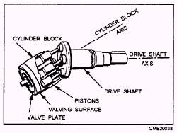
Figure 3-14.- Nine-piston radial piston pump. of controlling pressure. There are many types of automatic pressure control valves. Some of them merely provide an escape for pressure that exceeds a set pressure, some only reduce the pressure to a lower pressure system or subsystem, and some keep the pressure in a system within a required range. The most common pressure control valves are relief valves
(fig. 3-21), pressure regulators (fig. 3-22), pressure-reducing valves (fig. 3-23),
and counterbalance valves (fig. 3-24). DIRECTIONAL CONTROL VALVES.- Directional control valves are designed to direct the flow of fluid, at the desired time, to the point in a fluid power system where it will do work; for example, using a directional control valve to drive a ram back and forth in its cylinder. Various other terms are used to identity directional control valves, such as selector valve, transfer valve, and control valve. Directional control valves for hydraulic and pneumatic systems are similar in design and operation. However, there is one major difference. The return port of a hydraulic valve is ported through a return line to the reservoir, while the similar port in a pneumatic valve, commonly referred to as an exhaust port, is usually vented to the atmosphere. Directional control valves may be operated by differences in pressure acting on opposite sides of the valving element, or they may be positioned manually, mechanically, or electrically. Often two or more methods of operating the same valve will be used in different phases or its action.
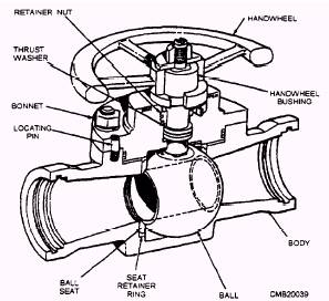
Figure 3-17.- Typical ball valve.
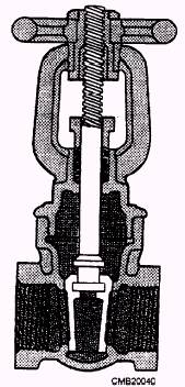
Figure 3-18.- Rising stem gate valve. Directional control valves may be classified in several ways. Some of the different ways are by the type of control, the number of ports in the valve housing, and the specific function of the valve. The most common method is by the type of valving element used in the construction of the valve. The most common types of valving elements used in a hydraulic 103
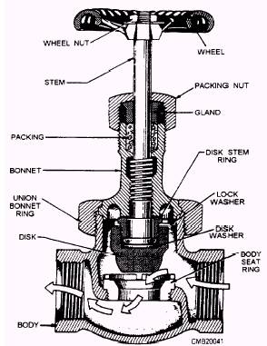
Figure 3-19.- Globe valve.
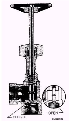
Figure 3-20.- Cross-sectional view of a needle valve.
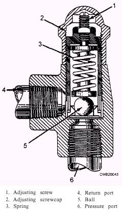
Figure 3-21.- Typical relief valve. system are the poppet (fig. 3-25), rotary spool (fig. 3-26), and sliding spool valves (fig. 3-27). |
 |
|
|