Custom Search
|
|
  |
|
|
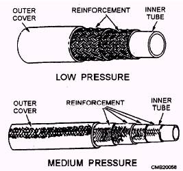
The three types of lines used in fluid power systems are tubing (semirigid), pipe (rigid), and hose (flexible). A number of factors are considered when the type of line is selected for a particular system. These factors include the type of fluid, the required system pressure, and the location of the system. For example, heavy pipe might be used for a large stationary system, but comparatively lightweight steel tubing is used in the automotive brake system. Flexible hose is requires in installations where units must be free to move relative to each other. PIPING AND TUBING.- The choice between pipe and tubing depends on system pressure and flow. The advantages of tubing include easier bending and flaring, fewer fittings, better appearance, better reusability, and less leakage. However, pipe is cheaper and will handle large volumes under high pressures. Pipe is also used where straight-line hookups are required and for more permanent installations. In either case, the hydraulic lines must be compatible with the entire system. Pressure loss in the line must be kept to a minimum for an efficient system. Pipes for hydraulic systems should be made of seamless cold-drawn mild steel. Galvanized pipe should NOT be used because the zinc coating could flake or scale, causing damage to the valves and pumps. Tubing used in fluid power systems is commonly made from steel, copper, aluminum, and, in some instances, plastic. Each of these materials has its own distinct advantages or disadvantages in certain applications. Copper. -The use of copper is limited to low-pressure hydraulic systems where vibration is limited. Copper has high resistance to corrosion and is easily drawn or bent. However, it is unsatisfactory for high temperatures and has a tendency to harden and break due to stress and vibration. Steel.- Tubing constructed of cold-drawn steel is the accepted standard in hydraulics where high pressures are encountered. Steel is used because of its strength, stability for bending and flanging, and adaptability to high pressures and temperatures. Its chief disadvantage is its comparatively low resistance to corrosion. There are two types of steel tubing- seamless and electric welded. Aluminum .- Aluminum is limited to low-pressure use, yet it has good flaring and bending characteristics. Plastic .- Plastic tubing lines are made from a variety of materials; nylon is the most suitable for use in low-pressure hydraulic applications ONLY. There are three important dimensions of any tubular product- outside diameter (OD), inside diameter (ID), and wall thickness. Sizes of pipe are listed by the nominal (or approximate) ID and wall thickness. Sizes of tubing are listed by the actual OD and the wall thickness. The material, the inside diameter, and the wall thickness are the three primary considerations in the selection of lines for the circulatory system of a particular fluid power system. The manufacturers of tubing and pipe usually supply charts, graphs, or tables which aid in the selection of proper lines for fluid power systems. These tables and charts use different methods for deriving the correct sizes of pipe and tubing. Line should normally be kept as short and free of bends as possible. However, tubing should NOT be assembled in a straight line, because a bend tends to eliminate strain by absorbing vibration and compensates for thermal expansion and contraction. Bends are preferred to elbows, because bends cause less of a power loss. A few of the incorrect and correct methods of installing tubing are shown in figure 3-35. FLEXIBLE HOSE.- Hose is used in fluid power systems where there is a need for flexibility, such as connection to units that move while in operation or to units attached to a hinged portion of the equipment. It is also used in locations that are subjected to severe vibration. Flexible hose is usually used to connect the pump to the system. The vibration that is set up by the operating pump would ultimately cause rigid tubing to fail. Flexible hose is designated by a dash number, which is the ID of the hose expressed in 16ths of an inch and is stenciled on the side of the hose. For example, the inside of a -16 hose is 1 inch. For a few hose styles, this is approximate and is not a true ID. Rubber hose is designed for specific fluid, temperature, and pressure ranges and is provided in various specifications. Flexible hydraulic hose is composed of three basic parts (fig. 3-36): Inner Tube.- The inner tube is a synthetic rubber layer that is oil-resistant. It must be smooth, flexible, and able to resist heat and corrosion. Reinforcement Layers.- The reinforcement layers vary with the type of hose. These layers (or plies) are constructed of natural or synthetic fibers, braided wire, or a combination of these. The strength of this layer depends upon the pressure requirement of the system.
Figure 3-36.- Flexible rubber hose construction.
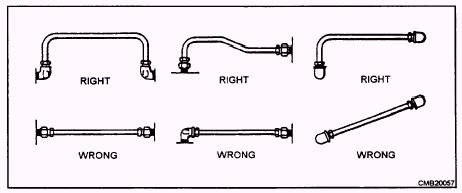
Flexible hose is provided in four-pressure ranges. Low pressure is used in a low-pressure system and for the exhaust lines of high-pressure systems. Medium-pressure hose is used in systems with pressures up to 1,200 psi; high-pressure hose is used with pressures up to 3,000 psi; and extra-high-pressure hose is used in systems with pressures up to 5,000 psi. High-and extra-high- pressure hoses normally come as complete assemblies with factory installed end fittings. Medium-and low-pressure hose are available in bulk and are usually fabricated locally. Flexible hose must NOT be twisted on installation, since this reduces the life of the hose considerably and may cause fittings to loosen as well. You can determine whether or not a hose is twisted by looking at the lay line that runs along the length of the hose. This lay line should not tend to spiral around the hose (fig. 3-37). Hose should be installed so that it will be subjected to a minimum of flexing during operation. Support clamps are not necessary with short installations, but with hoses of considerable length (48 inches for example), clamps should be placed not more than 24 inches apart. Closer supports are desirable and, in some cases, needed. Hose must NEVER be stretched tight between two fittings. About 5 to 8 percent of the total length must be allowed as slack to provide freedom of movement under pressure. When flexible hose is under pressure, it contracts in length and expands in diameter. Examples of correct and incorrect installations of flexible hose are shown in figure 3-37. |
 |
|
|