Custom Search
|
|
 
|
||
|
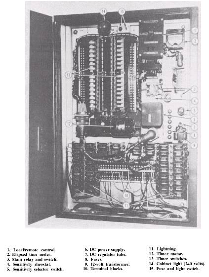
Master Sequence Timer Cabinet The master sequence timer cabinet has all of the controls for the strobe light system except the tower control unit. The cabinet is supplied from a 240-volt, phase-to-ground circuit. Our discussion of how the system operates is keyed to the numbers in figure 2-13. LOCAL/REMOTE CONTROL UNIT.\The local/remote control unit (No. 1) gives you a way to turn the system on locally or give control to the tower. In the center of this unit is a control knob with three positions: REMOTE/OFF/ LOCAL-ON. There are two red indicator lights above the control knob and two green lights below it. When the control knob is in the LOCAL-ON position, the system is turned on, and red lights will glow to indicate that the system is on LOCAL CONTROL. The green monitor lights should burn unless there is a fault in the system; in which case, they will go out. When the control knob is placed in the REMOTE position, the system can be turned on and off at the tower control unit. The red indicator lights will go out, but the monitor lights will continue to work as before. You should remember that the tower has no control except when the switch is in REMOTE. MONITOR AND CONTROL CHASSIS.\ The monitor and control chassis has several functions. They are as follows: 1. It de-energizes the monitor lights in both control units when a set number of lights stop working. 2. It has a step-down transformer to supply the voltages needed for control and indication. 3. It has a diode rectifier that supplies direct current for relay operation. 4. It has the fuses that protect the master sequence timer, the indicator circuits, and other components. The main power transformer in the monitor and control chassis is energized all the time from a local 240 volt ac supply. The secondary voltage from this transformer energizes the indicator lamp transformer and the transformer of the dc circuit. The indicator lamp transformer supplies 12 volts ac to the indicator lights in the local/remote control unit. The transformer for the dc power .
Figure 2-13.\Master sequence timer and controls.
will supply 95 volts ac to a bridge rectifier which supplies 120 volts dc to the dc monitor circuit. As long as the master control switch is on, power is fed to the tower control unit no matter what position the local/remote control unit switch is in. When the flasher control switch in the vault control unit is closed, the dc power interlock relay closes and energizes the monitor lights in the tower control unit. The unit responds in the same way as if the system were in full operation and working well. For this reason, the tower personnel must be notified when the switch in the local/remote control unit is in the OFF position. When the flasher control switch on the local/remote control unit is in the OFF or LOCAL-ON position, the red indicator lights tell you that the tower control unit is not in full operation. There is a monitor-sensing relay to monitor the operation of the strobe lights. When all the light units are working correctly, there will not be enough current through the coil of the monitorsensing relay to actuate the relay. A variable adjustable resistor can be adjusted so that there will be 7,333 ohms of resistance between the monitor-sensing relay and ground. A resistance of 7,333 ohms equals three 22-kilohm resistors in parallel. The monitoring circuit in each light unit has a 22-kilohm resistor. So, if you take the three 22-kilohm resistors out of the monitor control unit, the monitor-sensing relay actuates when at least three light units have ceased to work and their monitoring circuits are grounded, as described earlier. The sensitivity selector switch lets you reduce the number of malfunctioning lights needed to actuate the monitor-sensing relay by increasing the current flowing through its coil. There are three 22-kilohm resistors in the monitor control unit. Each of these three resistors simulates the effect of a grounded monitor connection to one of the lights. If the monitor-sensing relay is tripped, the monitor lights on the local/remote control unit will go out. At the same time, the monitor lights in the tower control unit go out and a buzzer sounds. The adjustment for the sensitivity of the monitor system is made at the monitor and control chassis in the master sequence timer cabinet. With all of the strobe lights operating and the sensitivity selector switch in the No. 1 UNIT position, the green monitor lamps should be on. If you turn the strobe light units on and the monitor lights do not come on, you need to adjust the sensitivity of the variable resistor (sensitivity rheostat). You need a small screwdriver to fit the slot in the rheostat shaft (No. 4). Turn the shaft clockwise as far as it will go (about half a turn). The green lamps should now be lit. Now, turn the rheostat counterclockwise slowly until the green lamps go out. Then turn the rheostat back clockwise slowly and stop as soon as the green lamps light. Check this setting by slipping a piece of paper between the contacts of one of the timer switches. The monitor lamps should go out. Remove the paper and turn the control switch to OFF for a few seconds and then to ON. The green lamps should now stay lit. Repeat this for different lamps and shift the rheostat slightly if you need to until you find a setting which will operate for any of the approach lights. Change the sensitivity selector switch to the No. 2 UNIT position and repeat the procedure while blocking two of the switches with pieces of paper. This is like having two strobe light units out and should have the same results as before. Restore the monitor lights the same as before. Repeat the procedure with the sensitivity switch in the No. 3 UNIT position while you block three of the timer switches. Now, check the operation of the monitor circuit with number 1, 2, and 3 strobe lights out. When you find the correct setting of the rheostat, no further adjustments should be needed. When your base requires the selector switch to be on the No. 1 UNIT position, then, in proper operation, if one strobe light fails, the alarm is stilled by just moving the selector switch to the No. 2 UNIT position. The switch is left in this position until the bad strobe light is fixed. At that time, the selector is returned to the No. 1 UNIT position. MASTER SEQUENCE TIMER.\The master sequence timer controls the order and rate of the triggering impulses to the light units. The timer has two camshafts driven by a motor (No. 12) through a reduction gear. The cams actuate 30 contacts (No. 13), one for each light unit, staggered on the shafts so that the contacts are closed in rapid succession as the shafts turn. Note that although there are 30 contacts, only 28 are used. Each of the 28 contacts is electrically connected to one of the light units. Thus, when the motor is energized, the contacts are momentarily closed in a predetermined sequence twice each second. This provides a series of 120-volt ac pulses to the trigger relays in the lights. These pulses are known as the timing circuit. Power for the 120-volt motor and the 120-volt timing pulses comes from the monitor and control chassis. An elapsed time meter (No. 2) is mounted next to the timer to show the total time the equipment has been in use; thus it serves as a guide for maintenance. Forty-five lightning arresters (No. 11) are installed in the lower part of the cabinet to protect the equipment from voltage surges on any of the lines. |
 |
|
|
||