| Tweet |

Custom Search
|
|
 
|
||
|
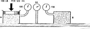
PRINCIPLES OF HYDRAULICS The word hydraulics is derived from the Greek word for water (hydor) plus the Greek word for a reed instrument like an oboe (aulos). The term hydraulics originally covered the study of the physical behavior of water at rest and in motion. However, the meaning of hydraulics has been broadened to cover the physical behavior of all liquids, including the oils that are used in modern hydraulic systems. The foundation of modern hydraulics began with the discovery of the following law and principle: Pascal's law-This law was discovered by Blaise Pascal, a French philosopher and mathematician who lived from 1623 to 1662 A.D. His law, simply stated, is interpreted as pressure exerted at any point upon an enclosed liquid is transmitted undiminished in all directions. Pascal's law governs the BEHAVIOR of the static factors concerning noncompressible fluids when taken by themselves. Bernoulli's principle-This principle was discovered by Jacques (or Jakob) Bernoulli, a Swiss philosopher and mathematician who lived from 1654 to 1705 A.D. He worked extensively with hydraulics and the pressure-temperature relationship. Bernoulli's principle governs the RELATIONSHIP of the static and dynamic factors concerning noncompressible fluids. Figure 2-13 shows the effect of Bernoulli's principle. Chamber A is under pressure and is connected by a tube to chamber B, also under pressure. Chamber A is under static pressure of 100 psi. The pressure at some point, X, along the connecting tube consists of a velocity pressure of 10 psi. This is exerted in a direction parallel to the line of flow, Added is the unused static pressure of 90 psi, which obeys Pascal's law and operates equally in all directions. As the fluid enters chamber B from the constricted space, it slows down. In so doing, its velocity head is changed back to pressure head. The force required to absorb the fluid's inertia equals the force required to start the fluid moving originally. Therefore, the static pressure in chamber B is again equal to that in chamber A. It was lower at intermediate point X. Figure 2-13 disregards friction, and it is not encountered in actual practice. Force or head is also required to overcome friction. But, unlike inertia effect, this force cannot be recovered again although the energy represented still exists somewhere as heat. Therefore, in an actual system the pressure in chamber B would be less than in chamber A. This is a result of the pressure used in overcoming friction along the way. At all points in a system, the static pressure is always the original static pressure LESS any velocity head at the point in question. It is also
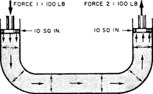
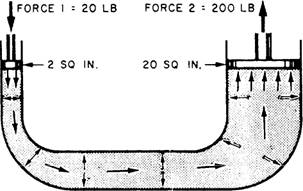
Figure 2-13.-Relationship of static and dynamic factorsBernoulli's principle. LESS the friction head consumed in reaching that point. Both velocity head and friction represent energy that came from the original static head. Energy cannot be destroyed. So, the sum of the static head, velocity head, and friction at any point in the system must add up to the original static head. This, then, is Bernoulli's principle; more simply stated, if a noncompressible fluid flowing through a tube reaches a constriction, or narrowing of the tube, the velocity of fluid flowing through the constriction increases, and the pressure decreases. When we apply a force to the end of a column of confined liquid, the force is transmitted not only straight through to the other end but also equally in every direction throughout the column. This is why a flat fire hose takes on a circular cross section when it is filled with water under pressure. The outward push of the water is equal in every direction. Water will leak from the hose at the same velocity regardless of where the leaks are in the hose. Let us now consider the effect of Pascal's law in the systems shown in figure 2-14, views A and B. If the total force at the input piston is 100 pounds and the area of the piston is 10 square inches, then each square inch of the piston surface is exerting 10 pounds of force. This liquid pressure of 10 psi is transmitted to the output piston, which will be pushed upward with a force of 10 psi. In this example, we are merely considering a liquid column of equal cross section so the areas of these pistons are equal. All we have done is to carry a 100-pound force around a bend. However, the principle shown is the basis for almost all mechanical hydraulics. The same principle may be applied where the area of the input piston is much smaller than the area of the output piston or vice versa. In view B of figure 2-14 the area of the input piston is 2 square inches and the area of the output piston is 20 square inches. If you apply a pressure of 20 pounds to the 2 square-inch piston, the pressure created in the liquid will again be 10 psi. The upward force on the larger piston will be 200 pounds-10 pounds for each of its 20 square inches. Thus, you can see that if two pistons are used in a hydraulic system, the force acting on each piston will be directly proportional to its area.
A. EQUAL INPUT AND OUTPUT AREA
B. UNEQUAL INPUT AND OUTPUT AREA Figure 2-14.-Principle of mechanical hydraulics. A. Equal input and output area. B. Unequal input and output area. |
 |
|
|
||