| Tweet |

Custom Search
|
|
 
|
||
|
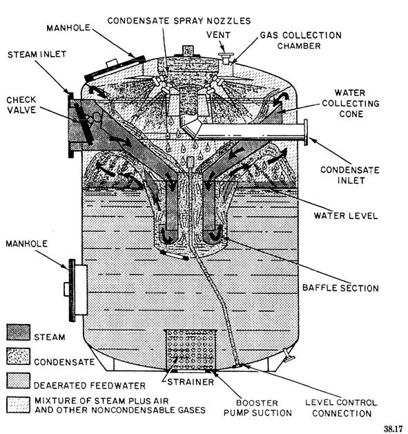
EXPANSION The EXPANSION area of the main steam system is that part of the basic steam cycle in which steam from the boilers to the main turbines is expanded. This removes the heat energy stored in the steam and transforms that energy into mechanical energy of rotation. The main turbines usually have a high-pressure (HP) turbine and a low-pressure (LP) turbine. The steam flows into the HP turbine and on into the LP turbine. Area B of figure - shows the expansion area of the main steam system. This portion of the main steam system contains HP and LP turbines. Each ship must produce enough feedwater for the boilers and still maintain an efficient engineering plant. Therefore, feedwater is used over and over again. As the steam leaves or exhausts from the LP turbine, it enters the CONDENSATE system. The condensate system is that part of the steam cycle in which the steam is condensed back to water. Then it flows from the main condenser toward the boilers while it is being prepared for use as feedwater. The components of the condensate system are (1) the main condenser, (2) the main condensate pump, (3) the main air ejector condenser, and (4) the top half of the deaerating feed tank (DFT). These components are shown in area C in Figure 3-1. The main condenser receives steam from the LP turbine. It condenses the steam into water. We will explain this process in the next chapter on boilers. The main condensate pump takes suction from the main condenser hot well. It delivers the condensate into the condensate piping system and through the main air ejector condenser. As its name implies, the air ejector removes air and noncondensable gases from the main condenser that leak or are discharged into it during normal operation. The condensate is used as a cooling medium for condensing the steam in the inter and after condensers of the main air ejector. FEED The DFT figure 3-2 is the dividing line between condensate and feedwater. The condensate enters the DFT through the spray nozzles and turns into feedwater in the reservoir section of the DFT. The DFT has three basic functions: To remove dissolved oxygen and noncondensable gases from the condensate To preheat the water To act as a reservoir to store feedwater to take care of fluctuations in feedwater demand or condensate supply The condensate enters the DFT through the condensate inlet. There it is sprayed into the dome of the tank by nozzles. It is discharged in a fine spray throughout the steam-filled top. The fine spray and heating of the condensate releases trapped air and oxygen. The gas-free condensate falls to the bottom of the tank through the water collecting cones, while the air and oxygen are exhausted from the tank vent. The collected condensate in the storage section of the DFT is now called feedwater and becomes a source of supply for the main feed booster pump. The main feed booster pump takes suction from the DFT and maintains a constant discharge pressure to the main feed pump. The main feed pump receives the water (delivered from the booster pump) and discharges it into the main feed piping system. Area D of Figure 3-l shows the path of the water from the DFT to the economizer. The discharge pressure of the main feed pump is maintained at 100 to 150 psig above boiler operating pressure on 600-psi plants. On 1200-psi plants, it is maintained at 200 to 300 psig above boiler operating pressure. The discharge pressure is maintained throughout the main feed piping system. However, the quantity of water discharged to the economizer is controlled by a feed stop and check valve or automatic feedwater regulator valve. The economizer is positioned on the boiler to perform one basic function. It acts as a preheater. The gases of combustion flow around the economizer tubes and metal projections that extend from the outer tube surfaces. The tubes and projections absorb some of the heat of combustion and heat the water that is flowing through the economizer tubes. As a result, the water is about 100 F hotter as it flows out of the economizer to the boiler.
Figure 3-2.-Deaerating feed tank. |
 |
|
|
||