| Tweet |

Custom Search
|
|
 
|
||
|
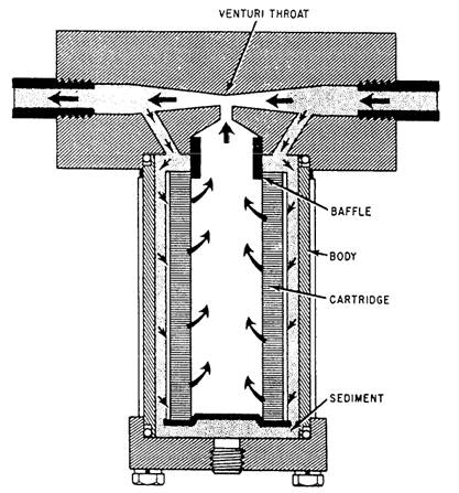
TYPES OF FILTERS In this section we will discuss the various filters (simplex, duplex, full flow, proportional flow, and indicator) that you will most frequently find installed in equipment. Simplex Filter The simplex filter has one or more cylindrically shaped fine mesh screens or perforated metal sheets. The size of the opening in the screens or the perforated metal sheets determines the size of particles filtered out of the fluid. The design of this type of filter is such that total flow must pass through a simplex filter. Duplex Filters Duplex filters are similar to simplex filters except in the number of elements and in provision for switching the flow through either element. A duplex filter may consist of a number of single element filters arranged in parallel operation, or it may consist of two or more filters arranged within a single housing. The full flow can be diverted, by operation of valves, through any single element. The duplex design is most commonly used in fuel or hydraulic systems because the ability to shift to an off-line filter when the elements are cleaned or changed is desirable without the system being secured. Full-Flow Filters The term full-flow applied to a filter means that all the flow into the filter inlet port passes through the filtering element. In most full-flow filters, however, there is a bypass valve preset to open at a given pressure drop and divert flow past the filter element. This prevents a dirty element from restricting flow excessively. Figure 9-47 shows a full-flow filter. Flow, as shown, is outto-in; that is, from around the element, through it to its center. The bypass opens when total flow can no longer pass through the contaminated element without raising the system pressure. The element is replaceable after removing a single bolt. Proportional-Flow Filters A proportional-flow filter may use the venturi effect to filter a portion of the fluid flow. The fluid can flow in either direction. As it passes through the filter body, a venturi throat causes an increase in velocity and a decrease in
Figure 9-47.-Full-flow filter.
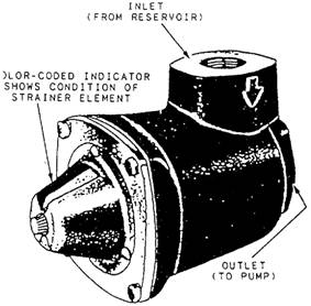
Figure 9-48.-Proportional-flow filter, pressure. The pressure difference forces some of the fluid through the element to rejoin the main stream at the venturi. The amount of fluid filtered is proportional to the flow velocity. Hence, the name proportional-flow filter. Indicating Filters Indicating filters are designed to signal the operator when the element needs cleaning. There are various types of indicators, such as color-coded, flag, pop-up, and swing arm. Figure 9-49 shows a color-coded indicating filter. The element is designed so it begins to move as the pressure increases due to dirt accumulation, One end is linked to an indicator that shows the operator just how clean or dirty the element is. Another feature of this type of filter is the ease and speed with which the element can be removed and replaced. Most filters of this kind are designed for inlet line installation.
Figure 9-49.-Color-coded indicating filter.
Filter/Separator The filter/separator is a two-stage unit consisting of a coalescer stage and a separator stage within a single housing. Each stage is made up of replaceable elements, the number of which is determined by such considerations as the capacity of the elements in gallons per minute (gpm) and the elements dirt retaining properties. Coalescer elements filter solids from the fluid and cause small particles of undissolved water to combine (coalesce) into larger drops of water that, because of their weight, will settle in the filter/separator sump. Separator elements are provided to remove any remaining free water that has not coalesced. Water that accumulates in the filter/separator sump is removed through a drain line, either automatically or manually. In-Line or Cone Filter In-line or cone filters have conical-shaped fine mesh screen or perforated metal sheet that is inserted into the system pipe and secured by a set of flanges. Its system application determines whether it is considered a filter or strainer. It is most commonly used in seawater systems, where it is considered a strainer. This type of filter is prohibited in fuel systems. MAINTENANCE Proper operation of filters, strainers, and filter separators is essential for satisfactory gas turbine and diesel engine performance. Besides clogging the systems with foreign matter, continued operation with unfiltered fluids results in accelerated pump wear and system degradation. Routine maintenance of filters, strainers, and filter/separators is adequately covered in NSTM, Chapter 541, "Petroleum Fuel Stowage, Use, and Testing," paragraphs 541-8.51 through 541-8.59. PIPING The control and application of fluid power would be impossible without a suitable means of conveying the fluid from the power source to the point of application. Fluid lines used for this purpose are called piping. They must be designed and installed with the same care applicable to other components of the system. To obtain this desired result, attention must be given to the various types, materials, and sizes of lines available for the fluid power system. The different types of lines and their application to fluid power systems are described in the first part of this section. The last part of this section is devoted to the various connectors applicable to the different types of fluid lines. |
 |
|
|
||