| Tweet |

Custom Search
|
|
 
|
||
|
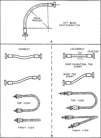
FLEXIBLE HOSE ASSEMBLIES The flexible hose assembly is a specific type of flexible device that uses reinforced rubber hose and metal end fittings. It is used to absorb motions between resiliently mounted machinery and fixed or resiliently mounted piping systems. The motions to be considered may be of either relatively large size due to high-impact shock or of smaller size due to the vibratory forces of rotating machinery. The configuration selected must contain enough hose to accommodate shock and vibratory motions without stressing the hose assembly or machinery to an unacceptable degree. Approved Flexible Hose Configurations The arrangements (or configurations) determined to give the best noise attenuation characteristics and to accommodate the motions of resiliently mounted equipment are shown in figures 9-50 and 9-51. The 90 "L" configuration
Figure 9-51.-Other approved single hose length configurations. (dogleg) is the preferred configuration; however, where space and piping arrangement prohibit the use of the "L" configuration, a 180 or "U" configuration may be used. The 90 "L" and 180 "U" configurations are shown as sketches A and B of figure 9-50. A configuration that uses a single length of hose bent to about 90 is approved where the hose does not bend below its specified minimum bending radius when the equipment moves to the maximum limits allowed by its mounts (view A of fig 9-51). The straight single hose configuration and the 180 single hose bend (view B of fig 9-51) are also approved for use where the hose size is less than 1 inch ID. Flexible connections that use rubber hose are not used in systems where the maximum continuous operating temperature is in excess of 200F. Hose is identified by the manufacturer's part number and the size or dash number. The dash number is the nominal hose inside diameter in sixteenths of an inch. Hose built to military specification (MILSPEC) requirements have the number of the specification and, where applicable, the class of hose, the quarter and year of manufacture, and the manufacturer's trademark. This information is molded or otherwise permanently repeated periodically on the hose cover (sometimes referred to as the "lay line marking"). Other information permanently marked on the hose cover is the manufacturer's code and the date of manufacture. For interpretations of commercial lay line markings, refer to the appropriate manufacturer's catalog or manual. Fitting Identification Use special care in identifying hose fittings because their designation is more complex than hose. A fitting suitable for connecting to a given hose size can end in more than one size and type of connection to the piping. A fitting, therefore, must be identified by the manufacturer's part number, the size of the end connection that joins the piping system, and the dash size to show the size hose to which it makes up. For interpretation of manufacturer markings, consult the appropriate manufacturer's manual. Fittings meeting military specification requirements have the specification number, class of fitting (where applicable), type, size, and manufacturer's trademark. A cross index between the manufacturers' designations and military specifications and information to correctly identify approved hoses and fittings can be found in Piping Devices, Flexible Hose Assemblies, volume 1, NAVSEA S6430-AE-TED-010. Inspection of Hose and Fittings Prior To Make-Up The basic inspection methods for hose and fittings are listed as follows: 1. Ensure that the hose and couplings are the correct ones for the intended use and that the age of the rubber hose does not exceed a shelf life of 4 years. Teflon and metal hose have no limiting shelf life. 2. Inspect for signs that the hose has been twisted. Use the hose lay line for a guide to determine whether or not any twist is present. If twisted, reiect. 3. Inspect for signs that the hose has been kinked or bent beyond its minimum bend radius. If suspect, reiect. 4. Inspect for signs of loose inner liner. If found, cut the hose to see if this condition exists throughout the entire length. If suspect. reject. 5. Visually check the inner liner and outer rubber cover of the hose for breaks, hairline cuts, or severe abrasions. If any suspect areas are found. reiect. 6. Inspect the fittings for defects, such as cracked nipples and damaged threads. If suspect, or if defects are found, reject. Procedures for making up hoses and fittings can also be found in the NSTM, chapter 505, or the appropriate manufacturer's catalog or manual, and are not covered here due to the many types available. Visual Inspection After assembling the hose and fittings, visually inspect the entire configuration to ensure the following: 1. The hose inner liner and outer cover is intact and contains no cuts or harmful abrasions. 2. The hose has not been twisted (check the lay line). 3. The circumferential chalk line on the hose next to the coupling has been drawn before the hydrostatic test. 4. The internal spring (if installed) is evenly spaced and flat against the inner liner. Ensure a gap exists between one of the end fittings and the end of the spring. Upon completion of visual inspection, hydrostatically shop test the hose assembly with fresh water. For each style and size of hose, test the pressure to ensure that it is twice the maximum allowable pressure shown in chapter 505 of the NSTM. When you test pressure, hold for not more than 5 minutes nor less than 60 seconds. When test pressure is reached, visually inspect the hose assembly for the following defects: 1. Leaks or signs of weakness 2. Twisting of the hose (this indicates that some twist existed before pressure was applied) 3. Slippage of the hose out of the coupling (a circumferential chalk line can help determine this) If any of these defects occur, reject the assembly. |
 |
|
|
||