| Tweet |

Custom Search
|
|
 
|
||
|
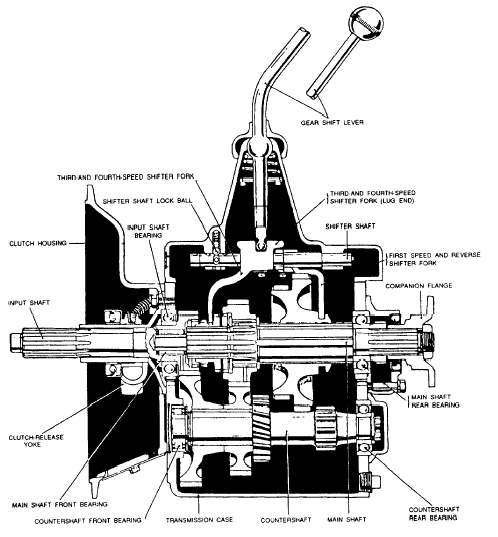
MULTIPLE-DISK CLUTCH A multiple-disk clutch is one having more than three plates or disks. Some have as many as 11 driving plates and 10 driven disks. Because the multiple-disk clutch has a greater frictional area than a plate clutch, it is suitable as a steering clutch on crawler types of tractors. The multiple-disk clutch is sometimes used on heavy trucks. Its operation is very much like that of the plate clutch and has the same release mechanism. The facings, however, are usually attached to the driving plates rather than to the driven disks. That reduces the weight of the driven disks and keeps them from spinning after the clutch is released. You may run into other types of friction clutches such as the lubricated plate clutch and the cone clutch. These types are seldom used on automatic equipment. However, fluid drives are largely replacing the friction clutches in automobiles, light trucks, and some tractors. For information on fluid drives (automatic trans-missions), refer to Construction Mechanic 3 & 2, NAVPERS 10644G-1, chapter 11.TRANSMISSION The transmission is part of the power train. It consists of a metal case filled with gears (fig. 13-5). It is usually located in the rear of the engine between the clutch housing and the propeller shaft, as shown in figure 13-1. The transmission transfers engine power from the clutch shaft to the propeller shaft. It allows the driver or operator to control the power and speed of the vehicle. The transmission shown in figure 13-5 and 13-6 is a sliding gear transmission. Many late model trucks have either a constant mesh or synchromesh trans-mission (explained later). However, both transmissions have the same principles of operation and the same gear ratios. A review of chapter 6 of this book will help you to understand the transmissions and power transfer mechanisms described in this chapter. FOUR-SPEED TRUCK TRANSMISSION The gear shift lever positions shown in the small inset in figure 13-6 are typical of most four-speed truck transmissions. The gear shifting lever, shown in A, B, C, D, and E of the figure, moves the position of the two shifting forks that slide on separate shafts secured in the transmission case cover. Follow the separate diagrams to learn what takes place in shifting from one speed to another. For example, as you move the top of the gear shift toward the forward left position, the lower arm of the lever moves in the opposite direction to shift the gears. The fulcrum of this lever is in the transmission cover. Shifting transmission gears requires the use of the clutch to disengage the engine. Improper use of the clutch will cause the gears to clash and may damage them by breaking the gear teeth. A broken tooth or piece of metal can wedge itself between two moving gears and ruin the entire transmission assembly. When you shift from neutral to first, or low, speed (fig. 13-6, A), the smallest countershaft gear engages with the large sliding gear. Low gear moves the truck at its lowest speed and maximum power. The arrows show the flow of power from the clutch shaft to the propeller shaft. The second-speed position is obtained by moving the gear shift lever straight back from the low-speed position. You will, of course, use the clutch when shifting. In figure 13-6, B, you will see that the next to the smallest countershaft gear is in mesh with the second largest sliding gear. The largest sliding gear (shift gear) has been disengaged, The flow of power has been changed as shown by the arrow. The power transmitted to the wheels in second gear (speed) is less, but the truck will move at a greater speed than it will in low gear if the engine speed is kept the same. In shifting from the second-speed to the third-speed position, you move the gear shift lever through the neutral position. You must do that in all selective gear transmissions. From the neutral position the driver can select the speed position required to get the power needed. In figure 13-6, C, notice that the gear shift lever is in contact with the other shifting fork and that the forward sliding gear meshes with the second countershaft gear. The power flow through the transmission has again been changed, as indicated by the arrow, and the truck will move at an intermediate speed between second and high. You shift into the fourth, or high-speed, position by moving the top of the shift lever back and to the right from the neutral position. In the high-speed position, the forward shift or sliding gear is engaged with the constant speed gear as shown in figure 13-6, D. The clutch shaft and the transmission shaft are now locked together, and the power flow is in a straight line. In high, the truck propeller shaft revolves at the same speed as the engine crankshaft, or at a 1 to 1 ratio. You shift to reverse by moving the top of the gear shift lever to the far right and then to the rear. Most trucks have a trigger arrangement at the gear shift ball to unlock the lever so that it can be moved from neutral to the far right. The lock prevents unintentional shifts into reverse. Never try to shift into reverse until the forward motion of the vehicle has been completely stopped. In figure 13-6, F, you can see how the idler gear fits into the transmission gear train. In figure 13-6, E, you can see what happens when you shift into reverse. An additional shifting fork is contacted by the shift lever in the far right position. When you shift to reverse, this fork moves the idling gear into mesh with the small countershaft gear and the large sliding gear at the same time. The small arrows in the inset show how the engine power flows through the transmission to move the propeller shaft and the wheels in a reverse direction. The different combination of gears in the transmission case makes it possible to change the vehicle speed while the engine speed remains the same. It is all a matter of gear ratios. That is, having large gears drive small gears, and having small gears drive large gears. If a gear with 100 teeth drives a gear with 25 teeth, the small gear will travel four times as fast as the large one. You have stepped up the speed. Now, let the small gear drive the large gear, and the large gear will make one revolution for every four of the small gear. You have reduced speed, and the ratio of gear reduction is 4 to 1. In the truck transmission just described, the gear reduction in low gear is 7 to 1 from the engine to the propeller shaft. In high gear the ratio is 1 to 1, and the propeller shaft turns at the same speed as the engine. This principle holds true for most transmissions. The second- and third-speed positions provide intermediate gear reductions between low and high. The gear ratio in second speed is 3.48 to 1, and in third is 1.71 to 1. The gear reduction or gear ratio in reverse is about the same as it is in low gear, and the propeller shaft makes one revolution for every seven revolutions of the engine.
Figure 13-7.-Constant-mesh transmission assemblysectional view. All transmissions do not have four speeds forward, and all do not have the same gear reductions at the various speeds. Passenger cars, for example, usually have only three forward speeds and one reverse speed. Their gear ratios are about 3 to 1 in both low and reverse gear combinations. You must remember, the gear reduction in the transmission is only between the engine and the propeller shaft. Another reduction gear ratio is provided in the rear axle assembly. If you have a common rear axle ratio of about 4 to 1, the gear reduction from the engine of a passenger car to the rear wheels in low gear would be approximately 12 to 1. In high gear the ratio would be 4 to 1 since the transmission would have no reduction of speed. |
 |
|
|
||