Custom Search
|
|
  |
|
|
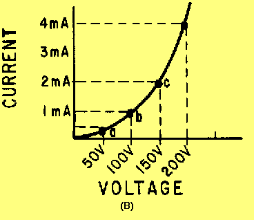
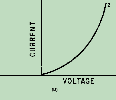
NONLINEAR IMPEDANCE You have studied that a linear impedance is one in which the resulting current is directly proportional to a change in the applied voltage. A nonlinear impedance is one in which the resulting current is not directly proportional to the change in the applied voltage. View (A) of figure 1-8 illustrates a circuit which contains a nonlinear impedance (Z), and view (B) shows its voltage-current curve. Figure 1-8A. - Nonlinear impedance circuit.
Figure 1-8B. - Nonlinear impedance circuit.
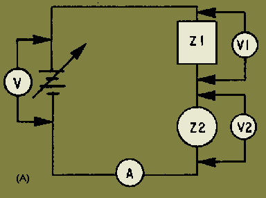
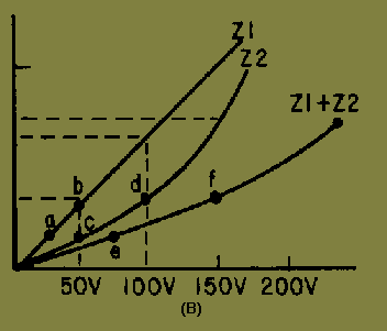
As the applied voltage is varied, ammeter readings which correspond with the various voltages can be recorded. For example, assume that 50 volts yields 0.4 milliampere (point a), 100 volts produces 1 milliampere (point b), and 150 volts causes 2.2 milliamperes (point c). Current through the nonlinear impedance does not vary proportionally with the voltage; the chart is not a straight line. Therefore, Z is a nonlinear impedance; that is, the current through the impedance does not faithfully follow the change in voltage. Various combinations of voltage and current for this particular nonlinear impedance may be obtained by use of this voltage-current curve. COMBINED LINEAR AND NONLINEAR IMPEDANCES The series combination of a linear and a nonlinear impedance is illustrated in view (A) of figure 1-9. The voltage-current charts of Z1 and Z2 are shown in view (B). A chart of the combined impedance can be plotted by adding the amount of voltage required to produce a particular current through linear impedance Z1 to the amount of voltage required to produce the same amount of current through nonlinear impedance Z2. The total will be the amount of voltage required to produce that particular current through the series combination. For example, point a (25 volts) is added to point c (50 volts) which yields point e (75 volts); and point b (50 volts) is added to point d (100 volts) which yields point f (150 volts). Intermediate points may be determined in the same manner and the resultant characteristic curve (Z1 + Z2) is obtained for the series combination. Figure 1-9A. - Combined linear and nonlinear impedances.
Figure 1-9B. - Combined linear and nonlinear impedances.
You should see from this graphic analysis that when a linear impedance is combined with a nonlinear impedance, the resulting characteristic curve is nonlinear. Some examples of nonlinear impedances are crystal diodes, transistors, iron-core transformers, and electron tubes. AC APPLIED TO LINEAR AND NONLINEAR IMPEDANCES Figure 1-10 illustrates an ac sine-wave generator applied to a circuit containing several linear impedances. A sine-wave voltage applied to linear impedances will cause a sine wave of current through them. The wave shape across each linear impedance will be identical to the applied waveform. Figure 1-10. - Sine wave generator applied to several impedances.
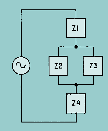
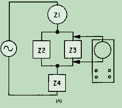
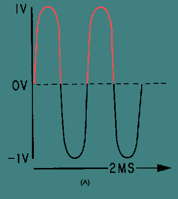
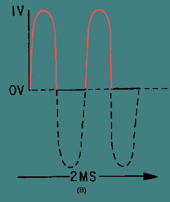
The amplitude, on the other hand, may differ from the amplitude of the applied voltage. Furthermore, the phase of the voltage developed by any of the impedances may not be identical to the phase of the voltage across any of the other impedances or the phase of the applied voltage. If an impedance is a reactive component (coil or capacitor), voltage or current may lead or lag, but the wave shape will remain the same. In a linear circuit, the output of the generator is not distorted. The frequency remains the same throughout the entire circuit and no new frequencies are generated. View (A) of figure 1-11 illustrates a circuit that contains a combination of linear and nonlinear impedances with a sine wave of voltage applied. Impedances Z2, Z3, and Z4 are linear; and Z1 is nonlinear. The result of a linear and nonlinear combination of impedances is a nonlinear waveform. The curve Z, shown in view (B), is the nonlinear curve for the circuit of view (A). Because of the nonlinear impedance, current can flow in the circuit only during the positive alternation of the sine-wave generator. If an oscilloscope is connected, as shown in view (A), the waveform across Z3 will not be a sine wave. Figure 1-12, view (A), illustrates the sine wave from the generator and view (B) shows the waveform across the linear impedance Z3. Notice that the nonlinear impedance Z1 has eliminated the negative half cycles. Figure 1-11A. - Circuit with nonlinear impedances.
Figure 1-11B. - Circuit with nonlinear impedances.
Figure 1-12A. - Waveform in a circuit with nonlinear impedances.
Figure 1-12B. - Waveform in a circuit with nonlinear impedances.
The waveform in view (B) is no longer identical to that of view (A) and the nonlinear impedance network has generated HARMONIC FREQUENCIES. The waveform now consists of the fundamental frequency and its harmonics. (Harmonics were discussed in NEETS, Module 9, Introduction to Wave-Generation and Wave-Shaping Circuits.) |
 |